Phownix2 Rev.
Table of Contents Important Information . . . . . . . . . . . . . . . . . . . . . . . . . . . 2 Required Installation Tools . . . . . . . . . . . . . . . . . . . . . . . . 2 Recommended Procedures . . . . . . . . . . . . . . . . . . . . . . . 2 Wiring Diagram . . . . . . . . . . . . . . . . . . . . . . . . . . . . . 3 20 Pin Connector . . . . . . . . . . . . . . . . . . . . . . . . . . . . 4 Installation Procedures. . . . . . . . . . . . . . . . . . . . . . . . . . . 5 Control Unit . . . . . . . . . . . . .
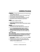
Important Information Required Installation Tools Voltmeter Wire Strippers Electric Drill & Bits Phillips Screw Driver Convoluted Tubing * Solder Gun * Wire Crimpers Shrink Tube or Electrical Tape * Optional Recommended Procedures 1. Test all circuits with a voltmeter. 2. Make all wiring connections with the supplied solderless crimp connectors. DO NOT twist wires or use “scotch-lok” connectors. 3. Route RED, RED/WHITE and BLACK wires from the control unit directly to the battery. 4.
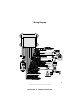
Wiring Diagram 3 Phoenix2 Rev.
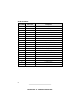
20 Pin Connector Pin Number Wire Color Description 1 RED Battery (+) 2 VIOLET Siren (-) Output 3 DARK BLUE Channel 2 (-) Output (Trunk Release) 4 LIGHT BLUE Channel 4 (-) Output 5 BLUE / YELLOW Channel 6 (-) Output 6 GRAY Armed (-) Output Prewired to Starter Disable Relay 7 TAN Hood / Trunk Switch (-) Input 8 PINK Ignition Output 9 LIGHT GREEN Second Stage Unlock (-) Output 10 BLACK Battery (-) 11 RED / WHITE Parking Light Polarity Input, (+) or (-) Input Select 12 RED /
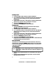
Installation Procedures Control Unit 1. Select a location under the dash that will allow you to use the tie wraps to securely fasten the control unit. 2. Mount the control unit as high as possible to ensure maximum range. 3. Do not mount the control unit near moving parts. 4. Avoid areas that are in the direct path of air blowing from the vents. 5. Route wires from this point, leaving slack for ease of service. Antenna 1. Do not shorten or lengthen the antenna. 2.
Valet Switch 1. Discuss placement with the vehicle owner. 2. Choose a location for the valet switch that is hidden, but convenient for the owner to access. 3. Drill a ¼" hole and mount the switch. 4. Route the valet switch wires to the control unit. 5. Plug the valet switch WHITE connector into the control unit WHITE plug. LED Indicator 1. Discuss placement with the owner. 2. Choose a location that is visible from both sides of the vehicle. 3. Drill a ¼" hole. 4.
Channel 6 Accessory (-) Output (Arm/Disarm + Option Buttons) The LIGHT BLUE/YELLOW wire provides a 0.75 second (-) output when activated whether the alarm is armed or disarmed. If the remote control button(s) is continually pressed, the signal will stay at ground as long as the button is held. Parking Lights 1. If the parking lights are positive trigger, connect the RED/WHITE wire to the battery positive (+) terminal through the 20 amp fuse.
Normally Closed 1. Locate the ignition switch wireloom under the dashboard. 2. Use a voltmeter to find the one wire that will show +12 volts while the ignition key is in the cranking cycle only. This should be the starter solenoid wire. 3. Cut the starter solenoid wire. Test by trying to crank the starter with the ignition key. If it will not crank, you have the correct wire. 4. Connect one YELLOW wire to the key side. 5. Connect the other YELLOW wire to the starter side. Normally Open 1.
9 Phoenix2 Rev.
10 Phoenix2 Rev.
11 Phoenix2 Rev.
12 Phoenix2 Rev.
Hood/Trunk Pin Switch 1. Locate the vehicle hood or trunk pin switch that shows ground when the hood or trunk is open only. 2. Connect the TAN wire to the vehicle hood or trunk switch wire. 3. If the vehicle does not have a hood or trunk switch, install a pin switch and connect it to the TAN wire. Siren 1. Choose a location in the engine compartment away from high heat engine components, moving parts and direct exposure to water. 2.
Programmable Features All system and remote control programmable features are accomplished by turning the ignition key to the "ON" position or starting the engine and flicking the valet switch on and off a preset number of times. The siren will chirp for audible programming confirmation. The system also allows you to add new remote controls in one step, delete lost or stolen remote controls or rearrange the factory preset remote control functions. 1.
Programming Table for System Features Feature Factory Setting No. of Chirps Secondary Action Active / Passive Arming Passive 4 Wait 3 seconds, the siren will chirp once for active, twice passive. Passive Door Lock OFF 5 Wait 3 seconds, the siren will chirp once for Off, twice for On. Passive Armed Confirmation ON 6 Wait 3 seconds, the siren will chirp once for Off, twice for On. 2 Pulse Unlock 1 Pulse 7 Wait 3 seconds, the siren will chirp once for 2 pulse, twice for 1.
Programming Table for Remote Controls Feature Factory Setting No. of Chirps Secondary Action Arm/Disarm ARM/DISARM Button 15 Press the ARM/DISARM button, the siren will chirp 1 time. Remote-Controlled Trunk Release Output TRUNK Button 16 Press the TRUNK button, the siren will chirp 2 times. Remote-Controlled Silent Arm/Disarm SILENT Button 17 Press the SILENT button, the siren will chirp 3 times.
Phoenix2 Rev.
© 1999 Avital Technologies, Inc. Part Number: 32-1270 Rev. A Phoenix2 Rev.
Phoenix2 Rev.