
Installation manual


Normally Closed
1. Locate the ignition switch wireloom under the dashboard.
2. Use a voltmeter to find the one wire that will show +12 volts while the
ignition key is in the cranking cycle only. This should be the starter
solenoid wire.
3. Cut the starter solenoid wire. Test by trying to crank the starter with the
ignition key. If it will not crank, you have the correct wire.
4.
Connect one YELLOW wire to the key side.
5.
Connect the other YELLOW wire to the starter side.
Normally Open
1.
Unplug the YELLOW wire from relay terminal 87A and insert the
YELLOW wire into relay terminal 87.
2. Locate the ignition switch wireloom under the dashboard.
3. Use a voltmeter to find the one wire that will show +12 volts while the
ignition key is in the cranking cycle only. This should be the starter
solenoid wire.
4. Cut the starter solenoid wire. Test by trying to crank the starter with the
ignition key. If it will not crank, you have the correct wire.
5.
Connect one YELLOW wire to the key side.
6.
Connect the other YELLOW wire to the starter side.
7. Program the alarm module for Normally Open (N.O.) starter disable (see
"Programming Table for Alarm Features").
Door Lock/Unlock
The alarm has on-board relays to lock and unlock the doors. It also has a
second unlock (-) output wire (GREEN ) that will allow you to do Two-Stage
Unlock. The second stage unlock wire provides a 400 ma, 0.75 second (-)
output when activated.
Two-Stage Unlock
I
CAUTION : Be sure to verify the type of door lock system you are
working with. Carefully follow the door lock/unlock diagrams on
pages 9-12.
1. Press the remote arm/disarm button once and the driver door only will
unlock.
2. Press the remote arm/disarm button again within 3 seconds and the
passenger doors will unlock.
8
Phoenix2 Rev. A - Installation Manual 0399
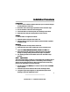
Normally Closed
1. Locate the ignition switch wireloom under the dashboard.
2. Use a voltmeter to find the one wire that will show +12 volts while the
ignition key is in the cranking cycle only. This should be the starter
solenoid wire.
3. Cut the starter solenoid wire. Test by trying to crank the starter with the
ignition key. If it will not crank, you have the correct wire.
4.
Connect one YELLOW wire to the key side.
5.
Connect the other YELLOW wire to the starter side.
Normally Open
1.
Unplug the YELLOW wire from relay terminal 87A and insert the
YELLOW wire into relay terminal 87.
2. Locate the ignition switch wireloom under the dashboard.
3. Use a voltmeter to find the one wire that will show +12 volts while the
ignition key is in the cranking cycle only. This should be the starter
solenoid wire.
4. Cut the starter solenoid wire. Test by trying to crank the starter with the
ignition key. If it will not crank, you have the correct wire.
5.
Connect one YELLOW wire to the key side.
6.
Connect the other YELLOW wire to the starter side.
7. Program the alarm module for Normally Open (N.O.) starter disable (see
"Programming Table for Alarm Features").
Door Lock/Unlock
The alarm has on-board relays to lock and unlock the doors. It also has a
second unlock (-) output wire (GREEN ) that will allow you to do Two-Stage
Unlock. The second stage unlock wire provides a 400 ma, 0.75 second (-)
output when activated.
Two-Stage Unlock
I
CAUTION : Be sure to verify the type of door lock system you are
working with. Carefully follow the door lock/unlock diagrams on
pages 9-12.
1. Press the remote arm/disarm button once and the driver door only will
unlock.
2. Press the remote arm/disarm button again within 3 seconds and the
passenger doors will unlock.