
Installation manual


Installation Procedures
Control Unit
1. Select a location under the dash that will allow you to use the tie wraps to
securely fasten the control unit.
2. Mount the control unit as high as possible to ensure maximum range.
3. Do not mount the control unit near moving parts.
4. Avoid areas that are in the direct path of air blowing from the vents.
5. Route wires from this point, leaving slack for ease of service.
Antenna
1. Do not shorten or lengthen the antenna.
2. Route the antenna away from the control unit.
3. Keep the antenna as far away from metal and wire harnesses as possible
to optimize range.
Wireloom
1. Plug the wireloom securely into the control unit.
2. Route wires from the control unit directly to each connection point.
3.
Separate the RED, RED/WHITE, BLACK, VIOLET and TAN wires.
4. Sleeve the wires with vinyl tubing or electrical tape and route them
through an existing rubber grommet into the engine compartment.
5. If an existing grommet is not available, drill a hole and install a snap
grommet.
Zone
2
™ Impact Sensor
The sensor must be firmly mounted on a solid metal surface inside the vehicle.
We recommend tie wrapping the sensor to the steering column housing or
steering column support bracket. DO NOT mount the sensor near moving
parts or in the direct path of an air duct opening.
1.
Plug the impact sensor BLUE 4-pin connector into the control unit BLUE
4-pin connector.
2. Route the impact sensor harness to the chosen mounting location.
3. Using the long tie wraps supplied, securely fasten the impact sensor
allowing access to the adjustment screws.
5
Phoenix2 Rev. A - Installation Manual 0399
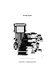
Installation Procedures
Control Unit
1. Select a location under the dash that will allow you to use the tie wraps to
securely fasten the control unit.
2. Mount the control unit as high as possible to ensure maximum range.
3. Do not mount the control unit near moving parts.
4. Avoid areas that are in the direct path of air blowing from the vents.
5. Route wires from this point, leaving slack for ease of service.
Antenna
1. Do not shorten or lengthen the antenna.
2. Route the antenna away from the control unit.
3. Keep the antenna as far away from metal and wire harnesses as possible
to optimize range.
Wireloom
1. Plug the wireloom securely into the control unit.
2. Route wires from the control unit directly to each connection point.
3.
Separate the RED, RED/WHITE, BLACK, VIOLET and TAN wires.
4. Sleeve the wires with vinyl tubing or electrical tape and route them
through an existing rubber grommet into the engine compartment.
5. If an existing grommet is not available, drill a hole and install a snap
grommet.
Zone
2
™ Impact Sensor
The sensor must be firmly mounted on a solid metal surface inside the vehicle.
We recommend tie wrapping the sensor to the steering column housing or
steering column support bracket. DO NOT mount the sensor near moving
parts or in the direct path of an air duct opening.
1.
Plug the impact sensor BLUE 4-pin connector into the control unit BLUE
4-pin connector.
2. Route the impact sensor harness to the chosen mounting location.
3. Using the long tie wraps supplied, securely fasten the impact sensor
allowing access to the adjustment screws.