
Installation manual


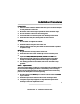


Valet Switch
1. Discuss placement with the vehicle owner.
2. Choose a location for the valet switch that is hidden, but convenient for
the owner to access.
3. Drill a ¼" hole and mount the switch.
4. Route the valet switch wires to the control unit.
5.
Plug the valet switch WHITE connector into the control unit WHITE plug.
LED Indicator
1. Discuss placement with the owner.
2. Choose a location that is visible from both sides of the vehicle.
3. Drill a ¼" hole.
4. Route the LED wires through the hole and press LED into place.
5. Route the LED wires to the control unit.
6.
Plug the RED LED connector into the control unit RED plug.
Ignition Input
1. Use a voltmeter to locate the one wire that shows +12 volts when the
ignition key is in the "ON," "CRANK" and "RUN" positions, and 0 volts
when the ignition key is in the "OFF" position.
2.
Connect the PINK wire to the vehicle ignition wire.
Channel 2 Accessory (-) Output
The DARK BLUE wire provides a 0.75 second ground (-) output when the
alarm is disarmed only. This is ideal for trunk release. If the remote control
button is continuously pressed, the signal will stay at ground as long as the
button is held.
NOTE: Most trunk releases are positive and require an optional relay.
Channel 4 Accessory (-) Output
The LIGHT BLUE wire provides a 0.75 second (-) output when activated
whether the alarm is armed or disarmed. If the remote control button is
continually pressed, the signal will stay at ground as long as the button is held.
6
Phoenix2 Rev. A - Installation Manual 0399