
Manual

VIDEO/AUDIO
MATRIX
(VAX-8404F)
4 In 4 Out
USER MANUAL V1.0
VAX-8404F
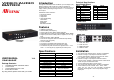
Package Contents-
1 AVLINK VX-8404F video/audio matrix
1 user manual
1 power adapter DC 12V 1.25A
2 rack rails, 8 screws
Any thing missed, please contact with your vendor.
Introduction
Through the video/audio matrix VX-8404F, you can display / play
different images / audio signals to 4 screens / speakers (or
earphones) through 4 PC. And you can also control the source of
image / audio by selecting PC signal source 1 ~ 4 or turning off
source input.
Video/Audio matrix is ideal for:
Test bench facilities
Data center
Help desks
Video broadcasting:
Presentation
Stock quotes
Timetables
Educational facilities
Features
Intelligent functionality.
With 350 MHz pixel frequency.
Support VGA, SVGA, UXGA, QXGA resolutions.
Support Multi-Sync video type include RGBHV, RGsB, RGBS.
Support synchronous Include positive, negative; TTL or 1Vpp
level.
Supports the DDC, DDC2, DDC2B.
Four sets of 7-Segment LED can indicate the input setting
status of input port quickly.
Can be cascaded.
The output is compatible with standard VGA card.
Extends the video signal up to 65 meter (213 feet).
The switches on panel can select PC signal source 1 ~ 4 as
OUT 1 ~ 4 or turning off any signal I/O port / all I/O ports.
Specifications
Function VAX-8404F
Video Input Connector 4x HD-15 Female
Video Output Connector 4x HD-15 Female
Audio Input Connector 4x 3.5φ Stereo Jack
Audio Output Connector 4x 3.5φ Stereo Jack
Select Switch 10
7-Segment LED 4
Max. Resolution 1920x1440 @ 85 Hz
Pixel Frequency 350 MHz
Cable Distance
(Device to Monitor)
65m (213 feet) Max.
Power Adapter (Min.) DC 12V 1.25A
Housing Metal
Weight 1065 g
Dimensions (LxWxH) 269x108x42 mm
-1-
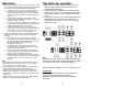
Technical Specifications
Input/Output Signal
Pin # Signal
Pin # Signal
1 Red video 9 NC
2 Green video 10 Ground
3 Blue video 11 NC
4 NC 12 ID1
5 Ground 13 Horizontal sync
6 Analog ground 14 Vertical sync
7 Analog ground 15 ID3
8 Analog ground
FRONT VIEW
1. Select Switch
2.
7-Segment LED
REAR VIEW
1. Input Power Jack
2. “
Audio Out” Port
3. “Audio In” Port
4. “Video Out” Port
5. “Video In” Port
Installation
1. Turn off the power switches of PC, screens, and speakers.
2. Use HD-15 image / 3.5φ earphone extension cable to
connect VGA interface / audio card in PC and the “Video
In“ & “Audio In“ jack of video/audio matrix.
3. Use HD-15 image / 3.5φ earphone extension cable to
connect screen, speaker, or earphone and the “Video Out“ &
“Audio Out“ jack of video/audio matrix.
4. Connect video/audio matrix to power supply.
5. Turn on the power switches of PC, screens, and speakers.
6. Control switches, which includes “Out1“, “Out2“, “Out3“,
“Out4“, “All“, “In1“, “In2“, “In3“, “In4“, and “OFF“, on panel can
get image / audio signals or turn off input signal through
output jack.
-2-