FRITZ!Box Fon WLAN 7570 vDSL Installation, configuration and operation
Legal Notice Legal Notice FRITZ!Box Fon WLAN 7570 vDSL This documentation and the software it describes are protected by copyright. AVM grants the nonexclusive right to use the software, which is supplied exclusively in object code format. The licensee may create only one copy of the software, which may be used exclusively for backup use. AVM reserves all rights that are not expressly granted to the licensee.
Contents Contents I CONNECTING AND OPERATION 7 1 Security and Handling . . . . . . . . . . . . . . . . . . . . . . . . . . . . . 7 2 FRITZ!Box Fon WLAN 7570 vDSL . . . . . . . . . . . . . . . . . . . . . . 9 2.1 2.2 Package Contents. . . . . . . . . . . . . . . . . . . . . . . . . . . . . . . . . . . . . . . . . . . 11 Operation Requirements . . . . . . . . . . . . . . . . . . . . . . . . . . . . . . . . . . . . . 12 3 Connecting . . . . . . . . . . . . . . . . . . . . . . . . . . . . . . . . . .
Contents 7 Telephone Connections . . . . . . . . . . . . . . . . . . . . . . . . . . . 35 7.1 7.2 7.3 7.4 Entering Your Phone Numbers. . . . . . . . . . . . . . . . . . . . . . . . . . . . . . . . .35 Configuring Telephony Equipment . . . . . . . . . . . . . . . . . . . . . . . . . . . . .36 Functions and Settings for Telephony. . . . . . . . . . . . . . . . . . . . . . . . . . .38 The Answering Machine Menu . . . . . . . . . . . . . . . . . . . . . . . . . . . . . . . . 41 8 USB Devices . . . . . . .
Contents 12 Directions for Operation . . . . . . . . . . . . . . . . . . . . . . . . . . .110 12.1 12.2 12.3 12.4 12.5 Symbols and Highlighting . . . . . . . . . . . . . . . . . . . . . . . . . . . . . . . . . . . 110 The Telephone Keypad. . . . . . . . . . . . . . . . . . . . . . . . . . . . . . . . . . . . . . 111 Instructions for Operation at the Telephone . . . . . . . . . . . . . . . . . . . . 111 LEDs . . . . . . . . . . . . . . . . . . . . . . . . . . . . . . . . . . . . . . . . . . . . . . . . .
Contents 5 Customer Service Guide . . . . . . . . . . . . . . . . . . . . . . . . . . 138 5.1 5.2 5.3 5.4 Documentation. . . . . . . . . . . . . . . . . . . . . . . . . . . . . . . . . . . . . . . . . . . . 138 Information in the Internet . . . . . . . . . . . . . . . . . . . . . . . . . . . . . . . . . . 139 Updates and Software . . . . . . . . . . . . . . . . . . . . . . . . . . . . . . . . . . . . . . 139 Support from the AVM Service Team. . . . . . . . . . . . . . . . . . . . . . . . . . .
Security and Handling I CONNECTING AND OPERATION 1 Security and Handling What to watch out for Security When working with the FRITZ!Box Fon WLAN 7570 vDSL, observe the following security instructions in order to protect yourself and the FRITZ!Box from harm. Do not install the FRITZ!Box during an electrical storm. Disconnect FRITZ!Box from the power supply during electrical storms. Never let liquids get inside the FRITZ!Box. Otherwise, electric shocks or short circuits may result.
Security and Handling For detailed information about the symbols, numerals and function keys used in the manual, see the section “Directions for Operation” from page 110.
FRITZ!Box Fon WLAN 7570 vDSL 2 FRITZ!Box Fon WLAN 7570 vDSL An Overview The FRITZ!Box Fon WLAN 7570 vDSL is a Private Branch Exchange (PBX) for making telephone calls via the Internet and the fixed-line network. The FRITZ!Box connects your computers directly with your DSL line. Each connected computer can establish an Internet connection over the FRITZ!Box. As a WLAN access point, FRITZ!Box offers you the possibility of connecting your computer to the DSL or VDSL line wirelessly.
FRITZ!Box Fon WLAN 7570 vDSL Connecting Computers Four computers can be connected directly to the FRITZ!Box using the four LAN ports. You can also connect a network hub or switch to the LAN ports so that even more computers can be connected to FRITZ!Box. WLAN Access Point The FRITZ!Box is a WLAN access point. All computers equipped with a WLAN adapter can be wirelessly connected to the FRITZ!Box.
Package Contents Network Devices Other network devices can also be connected to the network ports of the FRITZ!Box, for instance game consoles. Operating Systems Supported The FRITZ!Box can be connected to computers with Windows operating systems, the Linux operating system or Apple computers with the Mac OS X operating system. 2.
Operation Requirements 2.2 Operation Requirements In order to operate the FRITZ!Box, you must have the following: a Web browser that supports Java script (for instance, Internet Explorer version 6.0 or higher, or Firefox version 1.5 or higher) DSL line compliant with ITU G.992.1, ITU G.992.3, ITU G.992.5, or a VDSL line for connection via WLAN: computer with a WLAN adapter compliant with IEEE 802.11n draft 2.0, IEEE 802.11g, IEEE 802.11a or IEEE 802.
Connecting 3 Connecting Connecting FRITZ!Box This chapter contains instructions on the following topics: launching FRITZ!Box operation connecting FRITZ!Box to electrical power connecting one or several computers to the FRITZ!Box connecting FRITZ!Box to DSL/VDSL connecting FRITZ!Box to ISDN or the analog telephone line connecting ISDN terminal devices to the FRITZ!Box connecting analog terminal devices to the FRITZ!Box Please see the instructions about the placement of the FRITZ!Box in section “Security an
Launching Operation without the Installation Help CD At the conclusion of the Installation Help, you will be routed directly to the FRITZ!Box user interface. Launching Operation without the Installation Help CD If you do not want to use the Installation Help on the FRITZ!Box CD, then work through the instructions below in the recommended order: 1. Placement of FRITZ!Box; see the section “Security and Handling” from page 7. 2.
Mounting on a Wall 3.2 Mounting on a Wall Mount the wall holder included in the package on the wall. Mounting the wall holder for the FRITZ!Box Place the FRITZ!Box on the wall holder and slide it into position.
Connecting to Electrical Power Attaching the FRITZ!Box to the wall holder 3.3 Connecting to Electrical Power Connecting to the power supply Connecting Set aside the power supply unit out of the FRITZ!Box package.
Connecting the Computer(s) 1. Connect the power supply unit to the socket on the FRITZ!Box labeled “Power”. 2. Plug the other end into an AC power outlet. The green “Power/DSL” LED will begin flashing after a few seconds. 3.4 Connecting the Computer(s) If you would like to surf the web using the FRITZ!Box or to open the FRITZ!Box user interface, then you must connect a computer with the FRITZ!Box.
Connecting Computer(s) to the LAN Port 3.5 Connecting Computer(s) to the LAN Port If you want to connect a computer to one of the four LAN ports on the FRITZ!Box, make sure that your computer is equipped with a network adapter. A LAN port is usually designated by the icon at left or labeled “LAN”. Connecting a computer to a LAN port on the FRITZ!Box Connecting Set aside the network cable (yellow) from the FRITZ!Box package. 1. Switch on your computer.
Connecting More Computers to the LAN Ports Connecting More Computers to the LAN Ports Additional cables are required to connect further computers. In purchasing a LAN cable, note the instructions in the section “Network Cable” on page 115. You can connect a computer to any of the four LAN ports of the FRITZ!Box at any time.
Connecting Computer(s) Wirelessly via WLAN 1. Connect one end of the LAN cable to the uplink port of the network hub or switch. 2. Connect the other end of the cable to one of the LAN sockets on the FRITZ!Box. The FRITZ!Box and the network hub are now connected with each other. 3.6 Connecting Computer(s) Wirelessly via WLAN Using WLAN you can connect one or multiple computers with the FRITZ!Box wirelessly. The wireless WLAN connection is independent of the operating system used.
Using WLAN adapters from Other Manufacturers 4. Now insert the FRITZ!WLAN USB Stick N in the USB port of the computer. The security settings saved on the FRITZ!WLAN USB Stick N are applied to the computer. Now the FRITZ!Box and FRITZ!WLAN USB Stick N are connected with each other wirelessly For more information, see the manual for the AVM FRITZ!WLAN USB Stick N or the manual for the AVM FRITZ!WLAN USB Stick.
Using WLAN adapters from Other Manufacturers 3. SSID (name of the WLAN radio network) FRITZ!Box Fon WLAN 7570 vDSL Encryption method WPA (TKIP) or WPA2 (AESCCMP) Encryption WPA PSK Key The key is printed on the stickers on the base of the device and on the cover of the FRITZ!Box CD. Network mode Infrastructure Confirm your entries using the relevant button in the user interface (for instance, “OK” or “Connect”). Now your WLAN adapter and the FRITZ!Box are connected with each other wirelessly.
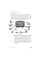
Connecting to the DSL/VDSL Line 8. Close the user interface and clear the connection between the FRITZ!Box and the computer. Remove the network cable (yellow). 9. Configure your WLAN adapter with the security settings entered in the FRITZ!Box. The WLAN connection between your WLAN adapter and the FRITZ!Box will be established. 3.7 Connecting to the DSL/VDSL Line Connecting to the DSL/VDSL splitter Connecting The gray cable is for connecting to the DSL/VDSL splitter.
Connecting to the ISDN Line 1. Connect the longer of the two gray branches of the cable to the port labeled “DSL/TEL”. 2. Then connect the other end of the cable to the corresponding socket on the DSL/VDSL splitter. If the end of the cable does not fit into the socket on the splitter, insert the end of the cable into the gray RJ45/RJ11 adapter included in the package and then insert the adapter into the socket on the DSL/VDSL splitter.
Connecting with the Analog Telephone Line Connecting Set aside the green cable delivered in the package. 1. Connect one branch of the cable to the socket on the FRITZ!Box labeled “ ”. 2. Insert the other branch of the cable into the socket of your ISDN NT. Now the FRITZ!Box and the ISDN line are connected. 3.9 Connecting with the Analog Telephone Line Your telephone line is either an analog line or an ISDN line.
Connecting Telephone, Fax, or Answering Machine 2. Then insert the black plug into the appropriate socket of your DSL/VDSL splitter. If the plug does not fit into the splitter, connect the end of the cable to the black RJ45/RJ11 adapter included in the package and then insert the adapter into the socket on the DSL/VDSL splitter. Now the FRITZ!Box and the analog telephone line are connected. 3.
Connecting ISDN Telephones 3.11 Connecting ISDN Telephones ISDN telephones can be connected to the FRITZ!Box and used to make calls via the Internet and the fixed-line network. With appropriate cabling, up to eight ISDN telephones can be connected. Connecting an ISDN telephone to the FRITZ!Box Connecting Use an ISDN cable to connect an ISDN telephone. 1. Connect one end of the ISDN cable with the ISDN telephone. 2. Connect the other end of the ISDN cable with the “S0int” port of the FRITZ!Box.
Connecting ISDN PBXs 3.12 Connecting ISDN PBXs If you have an ISDN PBX, you can connect this PBX to the FRITZ!Box. With the telephones connected to the PBX you can make calls both via the Internet and via the fixed-line network. The ISDN PBX must support a point-to-multipoint line. Connecting an ISDN PBX to the FRITZ!Box Connecting Use an ISDN cable to connect an ISDN PBX. 1. Connect one end of the ISDN cable with the ISDN PBX. 2.
Opening the User Interface 4 Opening the User Interface fritz.box The FRITZ!Box has a user interface that can be used in a web browser. The user interface presents information about the FRITZ!Box product, ports and connections. This is also where you configure settings for operation of the FRITZ!Box. The user interface can be opened from any computer connected with the FRITZ!Box. The settings are saved in the FRITZ!Box. Starting 1. Start a web browser on your computer. 2. Enter fritz.
Internet Connections 5 Internet Connections Setting Up the Internet Connection In order to allow Internet access with the FRITZ!Box, you must first configure the Internet connection in the FRITZ!Box user interface. The FRITZ!Box can be operated directly at the DSL or VDSL line. Alternatively, it can be connected to a cable modem, a DSL or VDSL modem, or a DSL router, or integrated into an existing network. 5.
Configuring the Internet Connection Manually 5. As a final step, click “Apply”. If the FRITZ!Box is connected to a cable modem, a DSL or VDSL modem or a router, or integrated into an existing network, you must also configure your Internet connection as described above. To do so, enable the expert mode in the “System / Expert Mode” menu.
The DECT Function 6 The DECT Function Cordless Telephony with FRITZ!Box Thanks to the integrated DECT function, the FRITZ!Box Fon WLAN 7570 vDSL can be used as a basis station for cordless phones. Every cordless phone (also known as a DECT telephone) that supports the DECT-GAP standard can be registered at the FRITZ!Box. A total of up to six cordless phones can be registered. 6.
Making an Internal Call to a Cordless Phone 6.2 Making an Internal Call to a Cordless Phone A cordless phone can also be called from another registered handset. To do so, proceed as follows: 1. Pick up the handset of a telephone connected to the FRITZ!Box. 2. Enter the keypad sequence corresponding to the cordless phone to be called. The keypad sequence is determined by the position at which the telephone is registered in the list of cordless phones in the FRITZ!Box user interface: 6.
Switching the DECT Function On and Off 6.4 Switching the DECT Function On and Off The DECT function is switched off upon delivery of the FRITZ!Box. Switching on the DECT function The DECT function is switched on when the first cordless phone is registered. Switching off the DECT function When the last cordless phone is logged off in the FRITZ!Box user interface, the DECT function is switched off automatically.
Telephone Connections 7 Telephone Connections Configuring FRITZ!Box for Telephony Using the FRITZ!Box you can make telephone calls via the Internet and the fixed-line network. Once you have connected the FRITZ!Box as described in the chapter “Connecting” from page 13, you can configure the FRITZ!Box for making telephone calls.
Internet Telephone Number Internet Telephone Number In order to be able to make calls via the Internet with the FRITZ!Box, you will need an Internet telephone number from an Internet telephony provider. You can enter multiple Internet numbers in the FRITZ!Box. The Internet numbers can be from one or from multiple different Internet telephony providers.
Settings for Telephony Devices answering machines If you have connected an analog answering machine (to “FON 1” or “FON 2”, for instance), configure it as an answering machine. The FRITZ!Box is also equipped with integrated answering machines, which can be enabled and configured in the “Settings / Advanced Settings / Telephony / Answering Machines” menu.
Functions and Settings for Telephony fax machine – kind of connection used to connect the fax machine with the FRITZ!Box – internal name for the fax machine – number used to send faxes: This entry defines whether outgoing faxes are sent via the Internet or the fixed-line network. – call acceptance: Here you define the numbers to which the fax machine should react.
Telephone Book Telephone Book A Telephone Book is at your disposal in the FRITZ!Box. If an AVM handset is registered at the FRITZ!Box, the Telephone Book can be transferred to the handset. Call Diversion With this function you can divert incoming calls to another number.
Alarm Alarm With this function you can use the telephones connected to the FRITZ!Box as alarm clocks. You can specify several different times for the alarm to go off. An individual telephone can be selected for the alarm function. Dialing Rules Dialing rules specify when calls are conducted on the fixedline network, and when they take place over the Internet. All connections to number ranges for which a dialing rule has been defined are established using the specified connection type.
The Answering Machine Menu 7.4 The Answering Machine Menu Main menu 1 Play back messages If no messages have been recorded, you hear two short audio signals and return to the main menu.
USB Devices 8 USB Devices USB Devices at the FRITZ!BoxUSB The FRITZ!Box is equipped with a USB port (also known as a USB host controller). Various USB devices can be connected to the host controller: an AVM FRITZ!WLAN USB Stick N or an AVM FRITZ!WLAN USB Stick a USB mass storage device (hard drive, memory stick) a printer a USB hub You can connect two USB mass storage devices and one USB printer, or three USB mass storage devices to the USB hub. The USB port of the FRITZ!Box supports the USB 1.
Accessing USB Devices 8.2 Accessing USB Devices Network Access As soon as a USB device is connected to the FRITZ!Box, all of its functions are available in the entire network: The files in the USB mass storage can be accessed from the network via FTP (File Transfer Protocol), or you can make the USB mass storage device available as a network storage device. USB printers are available as network printers.
Enabling the USB Remote Connection USB remote connection can be enabled for various USB devices, such as USB mass storage devices, printers and scanners. Please note that the FTP and USB network memory functions are not available as long as the USB remote connection is active for USB storage devices. With the FRITZ!Box USB remote connection you can enjoy the full range of functions of your USB devices. USB storage devices can also be used with special file formats like NTFS.
Disabling the USB Remote Connection 7. Open the “USB Remote Connection” menu and install the program for the USB remote connection on the computer from which you want to use the USB devices. Follow the instructions on the “USB Remote Connection” page. The program can be implemented in Windows Vista (32-bit) and Windows XP (32-bit) with Service Pack 2 or higher. 8. The next step is to specify for which kind of USB devices the USB remote connection should be enabled. Enable the desired options. 9.
USB Mass Storage Devices 8.4 USB Mass Storage Devices USB mass storage devices include hard drives and memory sticks. File Systems The USB mass storage supports the file systems FAT, FAT32 and NTFS. Connecting A USB storage device can be connected either directly to the USB port or via the USB hub (see the section “USB Hub” on page 55). Please also see the “Tips for Using USB Devices” on page 56.
Accessing the Data in the USB Mass Storage Devices Accessing the Data in the USB Mass Storage Devices USB storage devices connected to the FRITZ!Box directly or via a USB hub are displayed with their device name in the “USB Devices / Overview of Devices” menu on the user interface. FTP (File Transfer Protocol) All of the computers in the network can access the data in the USB mass storage simultaneously via FTP.
USB Printers The devices automatically communicate via Universal Plug and Play (UPnP). This technology allows the devices connected to each other by cable or radio network to perform automatic detection, recognize events, and exchange data with each other accordingly. With UPnP AV this technology has been expanded to audio and video contents. The FRITZ!Musikbox makes files available in the MP3, WMA or WAV format. 8.
USB Printers When the USB remote connection is enabled, all-inone printers (printers with supplementary fax or scanner functions) can also be used for faxing and scanning. If the USB printer is operated as a network printer, only the printing function is supported. If your printer is equipped with a status monitor, you can use this feature when the USB remote connection is enabled. If the printer is used as a network printer, it may not be possible to utilize the status monitor.
Configuring the Printer Port in the Windows Operating Systems Configuring the Printer Port in the Windows Operating Systems If the “FRITZ!Box” entry is already listed in the “Programs” group of the start menu of the computer, this means that the printer port is already configured on this computer. Otherwise, work through the following steps to configure the printer port: 1. Insert the FRITZ!Box CD in your CD-ROM drive. The installation Help is started. 2. Click the “View CD Contents” button. 3.
Installing Print Drivers in Windows XP/2000 7. You can enter a name for the printer in the “Printer Name” field. The operating system will use this name to administer the printer. 8. Conclude the installation by clicking “Finish”. Installing Print Drivers in Windows XP/2000 1. Open the start menu of the computer and click the “Printers and Faxes” entry (Windows XP) or click “Start / Settings / Printer” (Windows 2000). 2.
Setting Up Printers in SUSE Linux Systems Setting Up Printers in SUSE Linux Systems A USB printer can be connected to the USB port of the FRITZ!Box for use as a network printer. The printer is then available to all computers connected with the FRITZ!Box. Install the printer as “root” or “superuser”. 1. Open a console and enter the following command: lpadmin -p -E -v socket://: -m 2.
Setting Up USB Printers on Apple Computers Setting Up USB Printers on Apple Computers A USB printer can be connected to the USB port of the FRITZ!Box for use as a network printer. The printer is then available to all computers connected with the FRITZ!Box. 1. Under “Go / Utilities”, open the “Printer Setup Utility”. 2. Click “Add”. 3. Select “IP Printer”. 4. In the “Protocol” field, select the entry “HP Jet Direct – Socket”. 5. Enter in the “Address” field the IP address of the FRITZ!Box: 192.168.
FRITZ!WLAN USB Stick N and FRITZ!WLAN USB Stick Information about compatible printers or printer drivers is available in the Internet, for instance on the following page: http://gutenprint.sourceforge.net/p_Supported_ Printers.php3 8.6 FRITZ!WLAN USB Stick N and FRITZ!WLAN USB Stick The FRITZ!WLAN USB Stick N and the FRITZ!WLAN USB Stick are WLAN adapters manufactured by AVM for connection to a computer. Using a WLAN adapter you can connect the computer wirelessly with the FRITZ!Box.
USB Hub 1. Insert the your stick into the USB port on the FRITZ!Box. The WLAN security settings are transmitted automatically to the FRITZ!WLAN USB Stick. The “INFO” LED on the FRITZ!Box begins flashing rapidly. As soon as the “INFO” LED stops flashing, transmission of the settings has been concluded. 2. Remove the FRITZ!WLAN USB Stick from the device. 3. After the security settings have been transmitted automatically, you can insert the FRITZ!WLAN USB Stick in a computer.
Tips for Using USB Devices 8.8 Tips for Using USB Devices USB Devices When using USB devices at the USB port of the FRITZ!Box, please keep in mind the following; If more than one USB device without its own power supply is connected to the FRITZ!Box, note that, in accordance with the USB specification, the total current consumption may not exceed a value of 500 mA. Otherwise unspecified malfunctions with the USB devices or even damage to the FRITZ!Box may occur.
Configuration and Operation at the Telephone 9 Configuration and Operation at the Telephone FRITZ!Box Keypad Sequences Many of the FRITZ!Box functions and features can be configured and used over a telephone connected to a FRITZ!Box extension. Only tone-dialing (dual-tone multifrequency = DTMF) telephones can be used in configuration and operation. Pulse dialing telephones are not suitable.
Restoring Factory Settings Save Permanently N Pick up the handset. r91ss Save all settings permanently by dialing the sequence shown at left. O Hang up the handset. Restoring Factory Settings The FRITZ!Box can be reset to its condition upon delivery by restoring factory settings. All settings you made in the FRITZ!Box—including the configured Internet connection—are deleted when the factory settings are restored.
Do Not Disturb Do Not Disturb You can enable the Do Not Disturb function for any telephone connected to FRITZ!Box in the user interface. When Do Not Disturb is enabled, the telephone will not ring. In configuring this function you can choose between enabling the function immediately and selecting a specific time period. Immediately When Do Not Disturb is enabled immediately, no incoming calls will be signaled at the specified extension. The Do Not Disturb setting will remain enabled until it is disabled.
Alarm Disable Do Not Disturb r81s6s disables Do Not Disturb for extension Alarm The FRITZ!Box includes an alarm function. The alarm can be configured individually for each connected telephone. First enter on the telephone the time at which you would like to be awakened and save this entry. Then enable the alarm function. Example: The telephone should ring to wake you at 07:00 a.m. Enter the value “0700” as the
Call Diversion on the ISDN Line Call Diversion on the ISDN Line Call forwarding is performed by the ISDN operator’s switching station. To use call forwarding, FRITZ!Box must be connected to an ISDN line. Then this feature can be used to forward calls to an external line. Call forwarding is subject to charges by the network provider and cannot be used to forward calls to Internet numbers. In addition to call forwarding, there is also call diversion via the FRITZ!Box.
Call Diversion on the ISDN Line Call Forwarding Immediately for Any MSN N Pick up the handset. s21s Dial the sequence shown at left. sr Q Wait for the acknowledgement tone. O Hang up the handset. Call Forwarding Immediately for All MSNs N Pick up the handset. s21ssr Dial the sequence shown at left. Q Wait for the acknowledgement tone. O Hang up the handset. Disable Call Forwarding Immediately for Your Outgoing Caller ID N Pick up the handset.
Call Diversion on the ISDN Line Disable Call Forwarding Immediately for All MSNs Call Forwarding When Busy N Pick up the handset. s21ssr Dial the sequence shown at left. Q Wait for the acknowledgement tone. O Hang up the handset. Incoming calls are forwarded to the specified number only if a call is already being conducted using the number dialed. You can define call diversion for the local outgoing call number. The local outgoing call number is the first number you assigned to an extension.
Call Diversion on the ISDN Line Call Forwarding When Busy for All MSNs N Pick up the handset. s67ssr Dial the sequence shown at left. Q Wait for the acknowledgement tone. O Hang up the handset. Disable Call Forwarding When Busy for Your Outgoing Caller ID N Pick up the handset. s67sr Dial the sequence shown at left. Q Wait for the acknowledgement tone. O Hang up the handset. Disable Call Forwarding When Busy for Any MSN N Pick up the handset.
Call Diversion on the ISDN Line Call Forwarding Delayed Incoming calls are forwarded to the specified number if not answered at the number originally dialed within 20 seconds (about five rings). Call forwarding can be configured for your extension’s outgoing caller ID (the first number assigned to an extension), for any number (for instance, a telephone at the other FRITZ!Box extension), or for all numbers. All settings can be disabled at any time.
Call Diversion on the ISDN Line Disable Call Forwarding Delayed for Your Outgoing Caller ID N Pick up the handset. s61sr Dial the sequence shown at left. Q Wait for the acknowledgement tone. O Hang up the handset. Disable Call Forwarding Delayed for Any MSN N Pick up the handset. s61ssr Dial the sequence shown at left. Q Wait for the acknowledgement tone. O Hang up the handset. Disable Call Forwarding Delayed for All MSNs N Pick up the handset.
Call Diversion Call Diversion Incoming calls to the FRITZ!Box telephones can be diverted to a different extension or to an external number. In contrast to call diversion over FRITZ!Box, there is also call forwarding (call diversion via the central exchange). How to use call forwarding by phone is described in the section “Call Diversion on the ISDN Line” on page 61. Do not activate both call forwarding and call diversion at the same time.
Call Diversion Call Diversion After the Third Ring N Pick up the handset. r42s Dial the sequence shown at left. /s r91ss Save your settings if desired by dialing the sequence shown at left. O Hang up the handset. Call Diversion When Busy N Pick up the handset. r43s Dial the sequence shown at left. /s r91ss Save your settings if desired by dialing the sequence shown at left. O Hang up the handset.
Call Diversion Call Diversion Immediately by Ringing N Pick up the handset. r45s Dial the sequence shown at left. /s r91ss Save your settings if desired by dialing the sequence shown at left. O Hang up the handset. Disable Call Diversion N Pick up the handset. r40ss Dial the sequence shown at left. r91ss Save your settings if desired by dialing the sequence shown at left. O Hang up the handset.
Call Waiting Call Waiting Call waiting can be switched on or off for each extension. Some older terminal equipment connected to extensions may misinterpret the call waiting signal. This is especially true of fax machines and modems. If communication errors occur, you should disable call waiting for fax and modem extensions. See section “Waiting Calls” on page 79 for information about how to accept a call while another connection is active.
Caller ID Suppression for Outgoing Calls (CLIR) Caller ID Suppression for Outgoing Calls (CLIR) The CLIR (Calling Line Identification Restriction) function prevents your telephone number being displayed on the other party’s phone during outgoing calls. The CLIR function is disabled in the factory settings. You have the option of enabling this function permanently and then disabling it again. CLIR can also be used for individual connections.
Displaying the Incoming Caller ID (CLIP) Displaying the Incoming Caller ID (CLIP) The CLIP (Calling Line Identification Presentation) function makes the number of callers—external and internal—visible on your telephone display. This feature is only effective if your telephone supports CLIP. The CLIP function is enabled in the factory settings. This function can be permanently disabled and enabled again. Enable Display of Incoming Caller ID (CLIP) N Pick up the handset. r50
Connected ISDN Line Identification Restriction and Presentation (COLR/COLP) Transmission of the connected line’s number can be switched on and off for each extension individually. Transmission of the connected line’s number is permanently enabled in the factory settings. Enable Connected Line Identification Restriction (COLR) Permanently N Pick up the handset. r53s1s Dial the sequence shown at left to disable transmission of the connected line’s number.
Disabling Automatic Outside Dialing Disabling Automatic Outside Dialing The offers the possibility of disabling automatic outside dialing. This means that you will receive an internal dialing tone when you lift the handset at the corresponding extension. This makes sense at any extension which is used to make many internal calls, for instance, between the extensions of the FRITZ!Box. When automatic outside dialing is disabled, for an external call the 0 must be dialed before the telephone number.
Call Rejection on Busy (Busy on Busy) Call Rejection on Busy (Busy on Busy) Calls for an extension can be rejected using the “Busy on busy” feature. This means that the user receives a busy signal whenever the extension is busy. Enable Busy on Busy N Pick up the handset. r52s1s Dial the sequence shown at left. r91ss Save your settings if desired by dialing the sequence shown at left. O Hang up the handset. Disable Busy on Busy 9.2 N Pick up the handset. r52
Selecting the Outgoing Number and the Type of Connection Selecting the Outgoing Number and the Type of Connection For outgoing connections you can specify the kind of connection to be used for the next dialing procedure. For this entry you can use settings already made, or circumvent the settings currently configured. In this case the dialing rules are suspended for the given dialing procedure.
Making Internal Calls Dial Internal Calls with Automatic Outside Dialing N Pick up the handset. You can hear the external dial tone immediately, since the extension is set for automatic outside dialing. ss If you would like to make an internal call to one of the extensions, dial ss, followed by the number of the extension, for instance 1 or 2. ss50 If you would like to call all ISDN terminal devices for which no number has been configured, then dial ss50.
Group Call Group Call Place a group call to call all other extensions at the same time. Your call is connected with whichever extension answers first. Group Call N Pick up the handset. ss9 Dial the keypad sequences shown at left to call all free extensions. Picking up a Call from the Answering Machine Use this function to pick up incoming calls on your telephone that already have been taken by the answering machine. Pick up a Call N Pick up the handset. s09 Dial the sequence shown at left.
Waiting Calls Waiting Calls When the “Call Waiting” feature is enabled and you are conducting a call, you will be notified as soon as an external call arrives on your line. This call will be signaled by an acoustic signal in the handset. You can accept the connection with the new caller within 30 seconds. If you ignore the signal, the waiting call is rejected after 30 seconds. For instructions on how to turn the Call Waiting function on and off, see the section “Call Waiting” on page 70.
Call Back on No Response (CCNR) on the ISDN Line A maximum of five call-back requests can be enabled for each extension at any given time. Call-back on Busy (CCBS) M You have just dialed a number and now you hear the busy signal. 5 If the call is not answered, within twenty seconds, dial either the number 5 or Rs37r the sequence shown at left. Q Wait for the acknowledgement tone. O Hang up the handset. K As soon as the subscriber you dialed hangs up, your telephone will ring.
Call Back on No Response (CCNR) on the ISDN Line Enable Call Back on No Response (CCNR) M You have just dialed a number and hear a ring tone. 5 If the call is not answered, within twenty seconds, dial either the number 5 or Rs37r the sequence shown at left. Q Wait for the acknowledgement tone. O Hang up the handset. As soon as the party you dialed completes the conversation being conducted from her or his phone, your phone rings. N Pick up the handset.
Alternating Between Calls Alternating Between Calls Whenever you have one active connection and one caller on hold, you can switch from one call to the other as often as you want using the Hold button. Alternate Between Calls Call 1 You are talking to Caller 1. P R Press the Hold button. Caller 1 is now on hold. M To establish a second call, simply dial ss plus the desired extension number for an internal call, or the desired external number.
Three-Party Conference Call Three-Party Conference Call FRITZ!Box allows you to hold telephone conferences with two other people at once. Two external and one internal party, or two internal and one external party can conduct a conference call with each other. Hold a Three-Party Conference Call N Pick up the handset. M Dial the external number of the first party. Talk. R Press the Hold button.
Consultation / Hold Consultation / Hold The Consultation/Hold feature allows you to place an existing call on hold. You then may consult with someone else at your workplace or dial a second call. The party on hold does not hear the second conversation. Once you have finished the consultation, you can return to the original connection. Consultation / Hold Call 1 You are talking to Caller 1. P R Press the Hold button. Caller 1 is now on hold and you can consult someone else.
Transferring Calls Transferring Calls The “Call Transfer” function allows you to transfer a connection from one of FRITZ!Box's extension to another. Transfer Calls Call 1 You are talking to Caller 1. P R Press the Hold button. Caller 1 is now on hold. ss To establish a connection to Caller 2, dial the star key twice and then her or his extension number. Call 2 You can now talk with the other Caller 2. P O To transfer the Caller 1 to Caller 2, simply hang up the handset.
Explicit Call Transfer (ECT) Explicit Call Transfer from a Three-party Conference Call N Pick up the handset. M Dial the external number of the first party. Talk. R Press the Hold button. M Dial the number for your second external call. You can now conduct a second conversation while your first call is on hold. R3 Dial the sequence shown at left to begin a three-party conference call. D Now all three participants can confer together.
One-time Explicit Transfer on the ISDN Line One-time Explicit Transfer on the ISDN Line Explicit Call Transfer (ECT) is an ISDN feature that must be enabled by your ISDN provider and thus usually is subject to extra charges. If ECT has not been enabled on your line, you can program the telephone system to initiate a onetime explicit call transfer before connecting to two parties. When you end the connection, the other two parties will be connected to each other.
Suspending/Resuming a Call on the ISDN Line Suspending/Resuming a Call on the ISDN Line The “Suspend/Resume” feature, also known technically as Terminal Portability, allows you to suspend an existing connection and resume it at another point on the S0 bus. The connection can be resumed at a different ISDN terminal device (such as an ISDN telephone) that is connected to your BRI line along with the FRITZ!Box. You will hear an acknowledgement tone to indicate that the call has been successfully suspended.
Call Tracing (MCID) on the ISDN Line Call Tracing (MCID) on the ISDN Line You can use this function during a call or after the caller hangs up. For more information about this feature, contact your ISDN provider. Call Tracing (MCID) Rs39r Dial the sequence shown at left. Room Monitoring (Baby Monitor) The following key sequence enables the function for monitoring the sound level in a room. First enter the volume level (a value between 1 and 8). Enter a telephone number.
Using Keypad Messages After initiating a room monitoring phone call, the PBX cannot generate a new call until at least one minute has lapsed. You can disable the function by simply hanging up the handset of the telephone at which you enabled it. Using Keypad Messages The “keypad” function allows you to control services and features on the telephone line (ISDN/analog) by entering characters and strings on the telephone keypad. These keyboard entries are called keypad messages.
Troubleshooting 10 Troubleshooting Help for Errors This chapter provides concrete assistance if you are not able to open the user interface of your FRITZ!Box, if you are having problems with the WLAN connection, or if you want to change the IP settings on your computer. 10.1 Errors Opening the User Interface If an error message is returned when you open the user interface, this can have various causes. Check the possible causes and attempt to resolve the error.
Checking the Cable Connections Checking the Cable Connections The user interface of the FRITZ!Box does not appear in the window of your web browser. Possible Cause The cable connections are not secure. Remedy Make sure that all cable connections are plugged in securely. Check the Name Resolution The user interface of the FRITZ!Box cannot be opened by entering fritz.box. Possible Cause The name resolution of the FRITZ!Box does not work. Remedy 1.
Checking the IP Address Checking the IP Address The user interface of the FRITZ!Box cannot be reached at the address fritz.box nor at 192.168.178.1. Possible Cause The IP address set on the connected computer is inapplicable. Remedy Set the network adapter used to DHCP so that the IP address can be obtained via the DHCP server of the FRITZ!Box. Adjust the settings to those described in the section “IP Settings” from page 102.
Disabling Online Operation Disabling Online Operation The user interface does not appear in the window of your web browser. Possible Cause The web browser is set for offline operation. Remedy Configure the web browser for online operation. Using the example of Internet Explorer 6: 1. Open the “File” menu. 2. If a checkmark is displayed in front of “Work Offline”, click this line. The checkmark will be removed and Internet Explorer will switch to online operation.
Checking the CGI Settings 3. Under “Exceptions” enter: “fritz.box; 192.168.178.1; 169.254.1.1” and click “OK”. Checking the CGI Settings The user interface does not appear in the window of your web browser. Possible Cause The execution of CGI scripts is disabled in the web browser. Remedy Configure the web browser so that the execution of scripts is allowed in the user interface. Using the example of the Internet Explorer 6: 1. Select “Tools / Internet Options... / Security”. 2.
Checking the Security Software Checking the Security Software The user interface cannot be displayed in the web browser. Possible Cause Security software is blocking access to the user interface. Remedy Security software like firewalls can prevent access to the user interface of the FRITZ!Box. Configure exceptions for the FRITZ!Box in all of the enabled security software.
The WLAN Adapter Cannot Find FRITZ!Box 4. Start your Internet browser and enter FRITZ!Box’s fixed IP address: 169.254.1.1 The FRITZ!Box user interface opens. Once you have reached the FRITZ!Box user interface again, you should check the FRITZ!Box settings and correct them if necessary. 10.
Enabling WLAN Enabling WLAN The wireless network of the FRITZ!Box is not found by the WLAN adapter. Possible Cause WLAN is not enabled in the FRITZ!Box. If the “WLAN” LED on the FRITZ!Box is not lit up or is flashing, this means that WLAN is not enabled. Remedy Press the WLAN button on the FRITZ!Box. The “WLAN” LED begins flashing and then remains lit. This means that the WLAN function is enabled.
WLAN Connection Is Not Established 6. Click the “Apply” button. 7. Remove the network cable and try again to establish a connection via WLAN. 10.3 WLAN Connection Is Not Established Comparing the Security Settings for WLAN Make sure that the WLAN security settings registered in the FRITZ!Box agree with the security settings of the WLAN adapter. Here is how to view the WLAN security settings of the FRITZ!Box and print them out. 1. Connect the FRITZ!Box to a computer using a network cable.
Testing the WLAN Connection Without Security Settings Testing the WLAN Connection Without Security Settings Disable the WLAN security settings to test whether a WLAN connection between the FRITZ!Box and the WLAN adapter is possible at all. 1. Connect the FRITZ!Box to a computer using a network cable. Proceed as described in the section “Connecting Computer(s) to the LAN Port” from page 18. 2. Open the user interface in a web browser.
Installing the Patch for WPA2 with Microsoft WLAN Service Installing the Patch for WPA2 with Microsoft WLAN Service The WLAN connection to FRITZ!Box cannot be established using the Microsoft WLAN Service (WZC = Windows Zero Configuration) in Windows XP with Service Pack 2. Possible Cause The required Microsoft patch for WPA2 (IEEE 802.11i) may not be not installed. Remedy Support for WPA2 in Microsoft WLAN service was not available until the current patch for Microsoft Windows XP Service Pack 2.
IP Settings 6. Select a different radio channel from the “Select radio channel” list. 7. Click the “Apply” button. 8. Remove the network cable and check whether interference continues to occur. 10.4 IP Settings The FRITZ!Box is equipped with its own DHCP server. This means that the connected computers obtain their IP addresses from the FRITZ!Box. The connected computers must be configured such that they can receive their IP addresses automatically.
Obtaining an IP Address Automatically in Windows XP 6. On the “General” tab, enable the options “Obtain an IP address automatically” and “Obtain DNS server address automatically”. . Properties of the Internet protocol (TCP/IP) 7. Confirm your selection by clicking “OK”. If necessary, repeat steps 5 through 7 for the “Internet Protocol Version 6 (TCP/IPv6)” as well. The computer now receives an IP address from the FRITZ!Box. Obtaining an IP Address Automatically in Windows XP 1.
Obtaining an IP Address Automatically in Windows 2000 Properties of the Internet protocol (TCP/IP) 5. Confirm your selection by clicking “OK”. The computer now receives an IP address from the FRITZ!Box. Obtaining an IP Address Automatically in Windows 2000 1. Select “Start / Settings / Control Panel / Network and Dial-up Connections”. 2. Double-click to select the LAN connection with the network adapter bound to FRITZ!Box. 3. Click the “Properties” button. 4.
Obtaining an IP Address Automatically in Mac OS X Properties of the LAN connection of a network adapter 5. Enable the options “Obtain an IP address automatically” and “Obtain DNS server address automatically”. Properties of the Internet protocol (TCP/IP) 6. Confirm your selection by clicking “OK”. The computer now receives an IP address from the FRITZ!Box. Obtaining an IP Address Automatically in Mac OS X 1. Select the “System Preferences” in the Apple menu. 2.
Obtaining an IP Address Automatically in Linux The computer now receives an IP address from the FRITZ!Box. Obtaining an IP Address Automatically in Linux For comprehensive information and tips on the topic of network configuration in Linux, see, for example: http://www.tldp.org/HOWTO/NET3-4-HOWTO-5.
Uninstallation 11 Uninstallation Removing Software and Program Entries This chapter describes how to: disconnect the FRITZ!Box from the computer uninstall the FRITZ!DSL software package remove the printer port remove the FRITZ!Box program group. 11.1 Disconnecting the FRITZ!Box from the Computer LAN Port If the computer is connected to one of the LAN ports on the FRITZ!Box, simply remove the network cable.
Removing the Printer Port in Windows XP Removing the Printer Port in Windows XP 1. Open “start / Control Panel / Add or Remove Programs”. Make sure that the “Change or Remove Programs” button is selected in the left-hand column. 2. Select the “AVM FRITZ!Box Printer Port” entry from the list of “Currently installed programs”. 3. Click the “Change/Remove” button. This concludes the uninstallation of the printer port. Removing the Printer Port in Windows 2000 1.
Removing the Program Group in Windows XP Removing the Program Group in Windows XP 1. Open “start / Control Panel / Add or Remove Programs”. Make sure that the “Change or Remove Programs” button is selected in the left-hand column. 2. Select the “AVM FRITZ!Box Documentation” entry from the list of “Currently installed programs”. 3. Click the “Change/Remove” button. This concludes the uninstallation of the program group. Removing the Program Group in Windows 2000 1.
Directions for Operation 12 Directions for Operation Symbols, Keys and LEDs The following sections present important information and tips for operation of the FRITZ!Box Fon WLAN 7570 vDSL. 12.1 Symbols and Highlighting This symbol indicates useful hints to assist you in working with the FRITZ!Box. This symbol indicates important instructions that must be observed to avoid malfunctions. The table below explains the highlighting used in this manual.
The Telephone Keypad 12.2 The Telephone Keypad 0 through 9 Numeric keys s Asterisk key R Hold or Flash key r Pound key 12.3 Instructions for Operation at the Telephone M Dial a number. N Pick up the handset. O Hang up the handset. P Talk D Three-party conference call Q Wait for the acknowledgement tone. K You hear the ring tone. Enter an extension number (Ext.). In the place of the abbreviation
LEDs 12.4 LEDs Twelve LEDs are built into the top of the FRITZ!Box Fon WLAN 7570 vDSL, which flash or light up to display various connection statuses.
Handset and Ring Patterns LED Internet Status Meaning flashes there are messages in your mailbox (this function must be supported by your telephony carrier) Fixed Line on a telephone connection via the telephone line (ISDN/analog) is active flashes there are messages in your mailbox (this function must be supported by your telephony carrier) Here you can define what additional information should be displayed on the “INFO” LED.
Product Details II PRODUCT DETAILS AND USEFUL INFORMATION 1 Product Details FRITZ!Box Fon WLAN 7570 vDSL This chapter provides you with product details on FRITZ!Box Fon WLAN 7570 vDSL. You receive information on the cables and buttons, technical data and further details. 1.1 Cables and Buttons See the information in the following section on the individual cables and switches on the FRITZ!Box Fon WLAN 7570 vDSL.
Network Cable Network Cable Additional network cable is required if you would like to use all of the FRITZ!Box Fon WLAN 7570 vDSL network ports. The FRITZ!Box Fon WLAN 7570 vDSL network cable (yellow) is a standard Ethernet cable. If you need a replacement cable, a longer cable or an extension, use a standard STP-type (Shielded Twisted Pair, 1:1) CAT5 Ethernet cable. To extend the cable you will also need a standard CAT45 double coupling link to RJ5. You can use either straight cable or crosslink cable.
Technical Specifications 1.4 Technical Specifications Ports and Interfaces DSL/VDSL/telephone port – DSL/VDSL modem in accordance with the standard ITU G.992.1, ITU G.992.3 (ADSL2), ITU G.992.5 (ADSL2+), ITU G.994.1 (G.hs) – Telephone port for connecting to the analog network or ISDN Two a/b ports for connecting two extensions via RJ11 sockets One ISDN S0 NT port – S0 bus with support for ISDN telephony devices; the CIP services voice, telephony, audio 3.1 and fax G2/G3 are supported.
User Interface and Display User Interface and Display Configuration and status messages via a web browser on a connected computer Twelve LEDs indicate the condition of the device Physical Specifications Dimensions (WxDxH): approx.
Declaration of CE Conformity 1.
Disposal Indication of Countries The radio technology of this device is designed for use in all countries of the European Union and in Switzerland, Norway and Iceland. In France only indoor operation is permitted. 1.6 Disposal The symbols shown below mean that old appliances and electronic parts must be disposed of separate from household waste.
More about WLAN 2 More about WLAN AVM and WLAN WLAN (Wireless Local Area Network) is a radio technology that allows Ethernet networks and access to the Internet to be provided without cable connections. This allows multiple users to share one wireless Internet connection. 2.1 Standards The WLAN standards IEEE 802.11a, IEEE 802.11b, IEEE 802.11g and IEEE 802.11n (on the basis of the preliminary draft 2.0 of the standard) and IEEE 802.
Standards for the Throughput Rate Range The range within a WLAN is highly dependent on the following factors: the WLAN adapter used the structural conditions the amount of radio traffic on the same frequency band. Other WLAN networks, microwave ovens or Bluetooth transmitters (mobile telephones) may be active. IEEE 802.11a Because this standard works exclusively in the seldom used 5-GHz range, it offers the opportunity to transmit data relatively free of interference from external influences.
The Standard for Security Combining this standard with the 802.11g ensures compatibility with older WLAN adapters. The Standard for Security IEEE 802.11i The WPA2 security mechanism is defined in the IEEE 802.11i standard. WPA2 is an extension of the familiar security mechanism WPA (Wi-Fi Protected Access).
Encryption Encryption The most important security setting is encryption. FRITZ!Box supports the security mechanisms WEP (Wired Equivalent Privacy), WPA (Wi-Fi Protected Access) and WPA2 as follows: As part of the WEP mechanism a static key is determined to serve for the encryption of the user data. Enter the key in the WLAN security settings of the FRITZ!Box. All of the WLAN adapters in your wireless network must also use this key.
Encryption Recommendation If your WLAN adapter supports an encryption method that is more secure than the one preconfigured in the FRITZ!Box, you should select the more secure encryption method in your FRITZ!Box. To configure the best security settings possible with FRITZ!Box and your WLAN adapter, please note the following recommendations: If your WLAN adapter supports WPA2 in accordance with the 802.11i standard: – Enable WPA encryption. – Select the WPA mode “WPA2 (CCMP)” or “WPA+WPA2”.
Frequency Ranges 2.3 Frequency Ranges WLAN uses the frequency range around 2.4 GHz in the ISM band or, alternatively, the frequency range at 5 GHz. You can use both frequency ranges with the FRITZ!Box. 2.4-GHz Frequency Band A WLAN in the 2.4-GHz frequency band works in the same band as Bluetooth, microwave devices and many cordless telephones. This means that interference may occur within WLANs operated in the vicinity of such devices.
Frequency Ranges In the 5-GHz frequency band, your FRITZ!Box occasionally may change channels unexpectedly due to DFS (Dynamic Frequency Selection) if a “higher privileged user” simultaneously claims the selected channel. This can happen especially when military or civilian radar is used in the immediate vicinity. A prerequisite for use of the 5-GHz frequency band is that all WLAN adapters in the network support this frequency range in accordance with the IEEE 802.11a or IEEE 8002.11n standard. 2.
Frequency Ranges Allocation of the WLAN channels in the 2.4-GHz range: Channel Frequency (MHz) Channel Frequency (MHz) 1 2412 8 2447 2 2417 9 2452 3 2422 10 2457 4 2427 11 2462 5 2432 12 2467 6 2437 13 2472 7 2442 Allocation of the WLAN channels in the 5-GHz range: Channel Frequency (GHz) Channel Frequency (GHz) 36 5.180 108 5.540 40 5.200 112 5.560 44 5.220 116 5.580 48 5.240 120 5.600 52 5.260 124 5.620 56 5.280 128 5.640 60 5.300 132 5.
More about Network Settings 3 More about Network Settings FRITZ!Box and Networks The FRITZ!Box is delivered with preconfigured network settings. According to these settings, all computers connected with the FRITZ!Box are located in the same subnetwork. You can change any of these preconfigured settings, but should only do so if you are well versed in networking technology. The Glossary (see the chapter “Glossary” from page 142) explains concepts and terminology having to do with IP networks.
IP Address 3.1 IP Address The FRITZ!Box is delivered with an IP address preset. Factory Settings All computers are located in the enabled same IP network IP address 192.168.178.1 Subnet mask 255.255.255.0 DHCP server enabled The IP address and the corresponding subnet mask automatically yield the following values: Network address of the subnet 192.168.178.0 Entire IP address pool for the computers 192.168.178.2 192.168.178.253 You can change the preset IP address.
Reserved IP Addresses The subnet mask must correspond with that of the connected subnet. When the DHCP server of the FRITZ!Box is enabled, the addresses 20 through 200 in the fourth group of numerals of the IP address are reserved for the DHCP server. If none of the computers in your network has an address from this pool, the DHCP server can remain switched on. If one of the computers has a fixed address assigned from this pool, you should switch off the DHCP server.
DHCP Server 3.2 DHCP Server The FRITZ!Box is equipped with its own DHCP server. The DHCP server is enabled by default in the factory settings. Every time the operating system on a computer connected with FRITZ!Box is started, it is assigned an IP address by the DHCP server. Only one DHCP server may be active within any network. Factory Settings All computers are located in the same IP network enabled IP address 192.168.178.1 Subnet mask 255.255.255.
Fixed IP Addresses when the DHCP Server Is Enabled The computers can receive their IP addresses from the DHCP server only if the setting “Obtain an IP address automatically” is enabled in the their IP settings. For more information, see the section “IP Settings” from page 102.
Changing the DHCP Server Settings In the case of the preset IP address of the FRITZ!Box, the following IP addresses are available for assignment to the computers: 192.168.178.2 - 192.168.178.253 Each IP address can be assigned only once. Changing the DHCP Server Settings Proceed as follows to open the DHCP server settings: 1. Start a web browser on your computer. 2. Enter fritz.box in the address line of the browser. 3. Select the “Advanced Settings / System” menu in the “Settings” area. 4.
Disabling “All computers are located in the same IP network” The DHCP server of the FRITZ!Box assigns all of the computers connected with the FRITZ!Box an IP address from the address pool of the DHCP server. Address pool of the DHCP server 192.168.178.20 - 200 This means that all of the computers connected with the FRITZ!Box are located in the same subnet.
Disabling “All computers are located in the same IP network” Deactivating Interface Network Address of the Subnet LAN 1 192.168.178.0 LAN 2 like LAN 1 LAN 3 like LAN 1 LAN 4 like LAN 1 WLAN 192.168.182.0 Proceed as follows to disable the setting “All computers are located in the same IP network”: 1. Open your a web browser on your computer and enter fritz.box in the address line of the browser. 2. Select the “Advanced Settings / System” menu in the “Settings” area. 3.
More about Internet Telephony 4 More about Internet Telephony Voice over IP (VoIP) Internet telephony has already been in use for years, but today it allows even private customers the convenience familiar from conventional telephony, usually at significantly lower prices. Internet telephony has also made it considerably more convenient to use applications like conference calls and answering machines in networks.
Bandwidth Management 4.2 Bandwidth Management The FRITZ!Box is equipped with integrated bandwidth management. This function ensures that the speech quality during telephone calls over the Internet is not reduced by surfing activity. To do this, the FRITZ!Box adjusts all uploads and downloads to the currently available bandwidth. Because the FRITZ!Box also places a higher priority on Internet telephony connections over Internet data connections, unwelcome interference is largely avoided.
Customer Service Guide 5 Customer Service Guide Help on All Important Service Topics AVM is there to help should any questions or problems arise. Here you will find the important information you need, in the form of manuals, updates and support. MS Service Pack In many cases problems which arise during operation can be resolved by installing the current Microsoft Service Pack for your operating system. The current service packs can be obtained free of charge from Microsoft at the address: www.microsoft.
Information in the Internet 5.2 Information in the Internet On its web site AVM presents comprehensive information on your AVM products as well as new product announcements and new product versions. Frequently Asked Questions (FAQs) We would like to make our products as easy to use as possible. If you still have problems, sometimes a little tip is all you need to resolve them. That is why we present you with a selection of frequently asked questions. The FAQs can be viewed at the following address: www.
Support from the AVM Service Team 5.4 Support from the AVM Service Team Should problems with your FRITZ!Box arise, we recommend taking the following steps: 1. If you have questions about starting operation of your FRITZ!Box, please consult the chapter “Connecting” from page 13. 2. Please see the information in the section “Product Details” on page 114. 3. If you have any problems, seek “first aid” by consulting the chapter “Troubleshooting” from page 91.
Support by Fax Support by Fax If necessary, you can reach AVM Support at the fax number: +49 (0)30 / 39 97 62 66 The following information should be included in your fax to the Support team: Your name and address. An e-mail address or fax number at which you can be reached. the serial number of the FRITZ!Box The serial number is printed on the sticker attached to the base of the device. Support staff will always check this number to ensure that you are a registered user.
Glossary 6 Glossary ADSL abbreviation for Asymmetric Digital Subscriber Line Designates a fast kind of file transfer that works with standard copper cables and transports signals in both directions at different speeds (upstream at 640 Kbit/s and downstream at up to 9 Mbit/s). ADSL2 abbreviation for Asymmetric Digital Subscriber Line 2 ADSL 2 (G.992.3) is a further development of the ADSL norm (G.992.1/G.992.2).
Glossary ADSL-Controller An ADSL-Controller is an electronic hardware assembly that allows a computer to access an ADSL line. ADSL-Controllers are stationary equipment, included on internal ADSL cards (for the PCI bus) or in external ADSL modems (with USB or Ethernet ports). Alias Alias means different, else and also known as. An alias is often a short, catchy substitute for a long, complicated string of characters, for example, the actual name of the user J.Smith@my-internetprovider.
Glossary DNS abbreviation for Domain Name System Domain Name Service takes care of determining the IP address for a given domain name. Domain Name Service is running on every computer. It accepts the domain name entered by a user and inquires about the corresponding IP address at a DNS server known to the service. If a DNS server cannot answer the inquiry itself, it can inquire about the IP address (DNS resolution) at other DNS servers.
Glossary It works by transmitting the current IP address to a special DDNS server each time the IP address changes. Except for the few seconds between the cancellation of the old IP address and the notification of the new IP address, the computer can always be reached at the selected domain name. Dynamic IP address A dynamic IP address is an IP address valid only for the duration of one Internet or network session.
Glossary Especially effective firewalls go even further, analyzing and evaluating the contents of the packets and filtering them according to prescribed rules. Such techniques are included in a Stateful Packet Inspection Firewall, for instance. Firmware The firmware is saved in programmable components within a device.
Glossary If all packets that cannot be delivered in a local network always are to be transmitted to their given recipients via the same gateway, for this purpose the address of the gateway must be saved as the default gateway in the network configuration of the computer. Such a default gateway for the computer is negotiated automatically by the operating system or the dialing software whenever an ISDN-Controller or DSL-Controller establishes a connection to the Internet.
Glossary IP addresses can be public or private, and also fixed or assigned dynamically. See the corresponding entries in the glossary for more information. IP addressing Addressing is one of the main functions of the Internet Protocol (IP). Internet addresses can be written in decimal, octal or hexadecimal notation. The FRITZ!Box uses “dotteddecimal” notation: The four bytes of an address are represented by decimal numbers separated by dots.
Glossary IP network A network in which data exchange takes place on the basis of the Internet Protocol is called an IP network. Port So that a single network connection on a connection can be used by multiple applications to exchange data with remote sites at the same time, a computer administers what are known as ports for the IP-based protocols TCP and UDP. Ports substantiate the point of access for the data packets delivered via the IP Internet protocol.
Glossary service for access to incoming data packets and thus keep it open permanently. The private IP address of the given computer must be saved as the destination address for all of the packets arriving at the port. Typical server applications which require port forwarding are FTP and Web servers.
Glossary Subnet mask The subnet mask indicates which part of an IP address is the network address and which the address of the computer. The network address defines what is called the subnet. Example 1 IP address: 192.168.178.247 Subnet mask: 255.255.255.0 The assignment of the first three groups of numerals in the subnet mask indicates that the first three groups of numerals in the IP address define the network. The following addresses result: Network address of the subnet: 192.168.178.
Glossary Example 2 Network address of the subnet: 192.168.0.0 Address of the computer in the 192,168,178,247 subnet: IP address pool in the subnet: 192.168.0.0 - 192,168,255,255 The IP addresses 192.168.0.0 and 192.168.255.255 are reserved. This means that the addresses from 192.168.0.1 to 192.168.255.254 are available for assignment to the computers. TCP/IP abbreviation for Transmission Control Protocol / Internet Protocol TCP/IP is the “language” of the Internet.
Glossary Provider. The process of automatic configuration via TR-069 is initiated by the ADSL terminal device. First the user enters a security key and then the settings are retrieved from the Auto Configuration Server and implemented in the ADSL terminal device without any further interaction with the user. During this process all of the communication between the ADSL terminal device and the Auto Configuration Server takes place in encrypted form.
Glossary Update A more recent version of software or firmware is called an update. Updates are often free of charge, resolve minor programming errors, and sometimes also offer new functions. Upload This term designates the procedure of transmitting files from one’s own computer to another computer in the Internet.
Glossary already existing analog telephones to be used even when the computer is switched off. Various Internet Service Providers and telephony carriers provide SIP fixed-line gateways for this purpose. Such a gateway is used to produce voice connections between the Internet and conventional telephone networks.
Glossary The application possibilities for wireless network communication also overlap with Bluetooth technology. For mobile devices with very low power consumption Bluetooth is the more useful solution, however, as Bluetooth uses considerably less power than wireless LAN. What is more, Bluetooth technology is more flexible and thus offers a greater bandwidth of potential applications.
Index Index A connecting analog fixed-line network . . . . . . .25 answering machine . . . . . . . . . . . 26 computer. . . . . . . . . . . . . . . . . . . . . 17 configuration for analog equipment26 fax machine . . . . . . . . . . . . . . . . . 26 ISDN telephones . . . . . . . . . . . . . .27 LAN . . . . . . . . . . . . . . . . . . . . . . . . .18 multiple computers . . . . . . . . . . . .19 network hub/switch . . . . . . . . . . . .19 network port . . . . . . . . . . . . . . . . . .18 telephone . . . .
Index E K ECT . . . . . . . . . . . . . . . . . . . . . . . . . . . . 85 electrical power connecting to. . . . . . . . . . . . . . . . . 16 error search . . . . . . . . . . . . . . . . . . . . . 91 explicit call transfer . . . . . . . . . . . 85, 87 keypad sequences . . . . . . . . . . . . 57, 90 keys . . . . . . . . . . . . . . . . . . . . . . . . . . . 111 L LEDs. . . . . . . . . . . . . . . . . . . . . . . . . . . 112 legal notice . . . . . . . . . . . . . . . . . . . . . . .
Index R W registering cordless phones . . . . . . . . 32 registering cordless phones by other manufacturers . . . . . . . . . . . . . . . . . . . . . 32 rings . . . . . . . . . . . . . . . . . . . . . . . . . . 113 WEP security mechanism . . . . . . . . . .123 WLAN . . . . . . . . . . . . . . . . . . . . . . 20, 120 enabling / disabling. . . . . . . 58, 115 encryption. . . . . . . . . . . . . . . . . . .123 frequency range . . . . . . . . . . . . . . 125 security . . . . . . . . . . . . . . . . . . . .