FRITZ!Box Fon 5113 Installation, Configuration and Operation
Legal Notice Legal Notice FRITZ!Box Fon WLAN 7113 This documentation and the software it describes are protected by copyright. AVM grants the nonexclusive right to use the software, which is supplied exclusively in what is known as object code format. The licensee may create only one copy of the software, which may be used exclusively for backup use. AVM reserves all rights that are not expressly granted to the licensee.
Table of Contents Symbols and Highlighting . . . . . . . . . . . . . . . . . . . . . . . . . 6 I CONNECTING AND OPERATION . . . . . . . . . . . . . . . . . . . . . . 7 1 Security and Handling. . . . . . . . . . . . . . . . . . . . . . . . . . . . . 7 2 FRITZ!Box Fon WLAN 7113 . . . . . . . . . . . . . . . . . . . . . . . . . 9 2.1 2.2 Package Contents . . . . . . . . . . . . . . . . . . . . . . . . . . . . . . . . . . . . . . . . . 10 Operation Requirements . . . . . . . . . . . . . . . . . . . . . .
7 Configuration and Operation on the Telephone . . . . . . . 32 7.1 7.2 7.3 7.4 Instructions for Operation at the Telephone. . . . . . . . . . . . . . . . . . . . 33 Audible Signals. . . . . . . . . . . . . . . . . . . . . . . . . . . . . . . . . . . . . . . . . . . 34 Configuring on the Telephone . . . . . . . . . . . . . . . . . . . . . . . . . . . . . . . 35 Operation at the Telephone . . . . . . . . . . . . . . . . . . . . . . . . . . . . . . . . . 42 8 Troubleshooting . . . . . . . . . . . . . . .
3 More about Networks . . . . . . . . . . . . . . . . . . . . . . . . . . . . 89 3.1 3.2 3.3 3.4 3.5 3.6 3.7 Network Overview. . . . . . . . . . . . . . . . . . . . . . . . . . . . . . . . . . . . . . . . . 89 IP Settings . . . . . . . . . . . . . . . . . . . . . . . . . . . . . . . . . . . . . . . . . . . . . . . 90 UPnP Settings . . . . . . . . . . . . . . . . . . . . . . . . . . . . . . . . . . . . . . . . . . . . 90 IP Address . . . . . . . . . . . . . . . . . . . . . . . . . . . . . . . . . . . . .
Symbols and Highlighting Symbols and Highlighting The following sections present explanations about the symbols and highlighting used in this manual. This symbol indicates useful hints to assist you in working with the FRITZ!Box. This symbol indicates important instructions that must be observed to avoid malfunctions. The table below explains the highlighting used in this manual.
Security and Handling I 1 CONNECTING AND OPERATION Security and Handling What to Watch out for Safety Instructions When working with the FRITZ!Box Fon WLAN 71130, observe the following security instructions in order to protect yourself and the FRITZ!Box from harm. Do not install the FRITZ!Box during an electrical storm. Disconnect FRITZ!Box from the power supply during electrical storms. Never let liquids get inside the FRITZ!Box. Otherwise, electric shocks or short circuits may result.
Security and Handling If you would like to establish wireless connections between the FRITZ!Box and the computer, position the device at a central location. Make sure to keep sufficient distance from potential sources of interference like microwave devices or electric devices with large metal housings. For detailed information about the symbols, numerals and function keys used in the manual, see the sections “Symbols and Highlighting” on page 6 and “Instructions for Operation at the Telephone” on page 33.
FRITZ!Box Fon WLAN 7113 2 FRITZ!Box Fon WLAN 7113 An Overview The FRITZ!Box is a DSL modem that connects your computers directly with your DSL line. Each connected computer can establish an Internet connection over the FRITZ!Box. As a WLAN access point, FRITZ!Box offers you the possibility of connecting your computer to the DSL line wirelessly. The FRITZ!Box is a Private Branch Exchange (PBX) for making telephone calls via the Internet and the fixed-line network.
Package Contents Local Network All of the computers connected with the FRITZ!Box constitute a network and can share access to any files released for file sharing. Internet All of the computers connected to the FRITZ!Box can access the Internet. The FRITZ!Box works as a DSL router, making the Internet connection available to all connected computers. All connected computers can then use the Internet connection at the same time. Firewall The FRITZ!Box is equipped with an integrated firewall.
Operation Requirements 2.2 Operation Requirements In order to operate the FRITZ!Box, you must have the following: a Web browser that supports Java script (for instance, Internet Explorer version 6.0 or higher, or Firefox version 1.5 or higher) Internet connection: – DSL line, ITU G.992.1 standard Annex A, ITU G.992.3 standard Annex A, ITU G.992.
Connection 3 Connection Connecting FRITZ!Box This chapter contains instructions on the following topics: Launching FRITZ!Box Operation Connecting FRITZ!Box to electrical power Connecting one or several computers to the FRITZ!Box connecting FRITZ!Box to DSL. Connecting FRITZ!Box to the Analog Telephone Line Connecting analog terminal devices to the FRITZ!Box Please see the instructions about setting up the FRITZ!Box in section “Security and Handling” on page 7. 3.
Launching Operation without the Installation Help CD Launching Operation without the Installation Help CD If you do not want to use the Installation Help on the FRITZ!Box CD, then work through the instructions below in the recommended order: 3.2 1. Mounting FRITZ!Box; see the section “Security and Handling” from page 7. 2. Connecting FRITZ!Box to the power supply; see the section “Connecting to Electrical Power” on page 13. 3.
Connecting to the Computer Connecting Set aside the power supply unit out of the FRITZ!Box package. 1. Connect the power supply unit to the socket on the FRITZ!Box labeled “Power”. 2. Plug the other end into an AC power outlet. The green “Power/DSL” LED will light up after a few seconds to indicate that the device is ready for operation. 3.
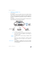
Connecting Computers to the LAN Port 3.4 Connecting Computers to the LAN Port If you would like to connect a computer to the LAN port of the FRITZ!Box, make sure the computer is equipped with a LAN port (network adapter). A LAN port is usually designated by the icon at left or labeled “LAN”. Connecting a computer to a LAN port on the FRITZ!Box Connecting Set aside the network cable (red) from the FRITZ!Box package. 1. Switch on your computer. 2.
Connecting a Network Hub or Switch Connecting a Network Hub or Switch You can connect a network hub or switch to the LAN port if you would like to connect multiple computers to the FRITZ!Box via LAN. Connecting FRITZ!Box to a network hub Connecting Set aside the network cable (red) from the FRITZ!Box package. 1. Connect one end of the LAN cable to the uplink port of the network hub or switch. 2. Connect the other end of the cable to the socket on the FRITZ!Box labeled LAN.
Connecting Computer(s) Wirelessly via WLAN 3.5 Connecting Computer(s) Wirelessly via WLAN Using WLAN you can connect one or multiple computers with the FRITZ!Box wirelessly. The wireless WLAN connection is independent of the operating system used. Each computer to be connected to the FRITZ!Box via WLAN must support WLAN, by means of a compatible WLAN adapter, for instance the FRITZ!WLAN USB Stick. For more information on WLAN, see the section “More about WLAN” from page 77.
Connect Using a WLAN Adapter Connect Using a WLAN Adapter You can connect computers with the FRITZ!Box wirelessly as soon as you have installed a WLAN adapter and configured WLAN software. Installing 1. Switch on your computer. 2. Install a WLAN adapter, for instance the FRITZ!WLAN USB Stick, on your computer along with the appropriate software. Please take note of the instructions in the documentation of the adapter.
Connect Using a WLAN Adapter Sticker with sample values 6. Confirm your entries using the relevant button in the user interface (for instance, “OK” or “Connect”). The WLAN connection is established. 7. Now read the security instructions in the section “Security” from page 79. Further WLAN settings can be configured in the user interface of your FRITZ!Box. See the section “Opening the User Interface” on page 23 for instructions on how to open the interface.
Connecting DSL and the Telephone Line 4. In the “WLAN / WLAN Security” menu, select WEP encryption and enter the network key you have chosen. 5. Click the “Apply” button. A window is displayed with the WLAN security settings. Print out the page by clicking “Print Page”. The data in the printout will be needed for the WLAN configuration of your WLAN adapter. 3.6 6. Close the user interface. 7. Remove the network cable connecting the computer and the FRITZ!Box.
Connecting with the Analog Telephone Line 1. Connect the longer of the two gray ends of the cable to the port labeled “DSL/TEL”. 2. Then connect the shorter, gray end of the cable to the socket on the DSL splitter labeled “DSL”. The black branch of the Y-shaped cable is for connection to the telephone line (see the sectionspage 21). The green “Power” LED stops flashing after a short time and remains lit to signalize that FRITZ!Box is ready for Internet connections over DSL. 3.
Connecting Telephone, Fax, or Answering Machine Connecting Set aside the Y-shaped cable (gray-black) delivered in the package. This cable is a combined DSL/telephone cable. 1. Connect the longer gray end of the cable to the socket on the FRITZ!Box labeled “DSL/TEL”. 2. Then insert the black plug into the appropriate jack of your DSL splitter. Now the FRITZ!Box and the analog telephone line are connected. 3.
Opening the User Interface 4 Opening the User Interface fritz.box The FRITZ!Box has a user interface that can be used in a web browser. The user interface presents information about the FRITZ!Box product, terminals and connections. This is where you configure all of the settings for operating the FRITZ!Box. The user interface can be opened from any computer connected with the FRITZ!Box. The settings you configure are saved in the FRITZ!Box. Starting 1. Start a web browser on your computer. 2.
Save Settings Be sure to use a password you can remember easily. If you forget the password, the only way to access the FRITZ!Box is to restore the factory settings. All settings made during operation will be overwritten. Then you can open the user interface again in order to reconfigure your settings or restore the settings you saved during previous operation. 4.2 Save Settings The settings you made in the FRITZ!Box can be saved as a file on your computer.
Internet Connections 5 Internet Connections Setting Up Internet Connections In order to allow Internet access with the FRITZ!Box, you must first configure the Internet connection in the FRITZ!Box user interface. The FRITZ!Box can be operated directly at the DSL line. Alternatively, it can be connected to a cable modem, a DSL modem, or a DSL router, or integrated into an existing network.
Surfing the Net 4. Select the setting “Use one Internet connection for all computers (router)” if this setting is not already configured. 5. Enter in these fields the Internet account information you received from your Internet Service Provider. Take advantage of the Help available in the FRITZ!Box user interface for more information and instructions. 6. As a final step, click “Apply”.
Telephone Connections 6 Telephone Connections Configuring FRITZ!Box for Telephony Using the FRITZ!Box you can make telephone calls via the Internet and the fixed-line network. Once you have connected the FRITZ!Box as described in the chapter “Connection” from page 12, you can configure the FRITZ!Box for making telephone calls.
Entering New Internet Telephone Numbers Entering New Internet Telephone Numbers In order to be able to make calls via the Internet with the FRITZ!Box, you will need an Internet telephone number from an Internet telephony carrier. Enter the Internet telephone number in the FRITZ!Box. You can enter multiple Internet numbers in the FRITZ!Box. The Internet numbers can be from one or from multiple different Internet telephony providers.
Settings for Telephony Devices Settings for Telephony Devices Telephony equipment like telephones, faxes and answering machines can be connected to the FRITZ!Box. The “Configure Telephony Devices” Wizard can assist you in configuring the necessary settings for all telephony devices.
Telephony Functions 6.3 Telephony Functions More functions and settings options for telephony are available in the “Settings / Advanced Settings” area, in the “Telephony” menu. Call List The Call List displays outgoing calls and sent faxes, incoming calls and faxes, as well as incoming calls in absence. If the number of a caller or someone called is entered in the Telephone Book, the Call List will display the name from the Telephone Book. The Call List can be saved as a file.
Alarm Menu The command for blocking calls is located in the “Settings / Advanced Settings” area, in the “Telephony / Calls” menu. Alarm With the alarm function you can use the telephones connected to the FRITZ!Box as alarm clocks. You can specify several different times for the alarm to go off. An individual telephone can be selected for the alarm function. Menu The “Alarm” function is located in the “Settings / Advanced Settings” area, in the “Telephony” menu.
Configuration and Operation on the Telephone 7 Configuration and Operation on the Telephone FRITZ!Box Keypad Sequences Many of the FRITZ!Box functions and features can be configured and used over a telephone connected to a FRITZ!Box extension. Only tone-dialing (dual-tone multifrequency = DTMF) telephones can be used in configuration and operation. Pulse dialing telephones are not suitable.
Instructions for Operation at the Telephone 7.1 Instructions for Operation at the Telephone The table explains the symbols used in this chapter: M Dial a number. N Pick up the handset. O Hang up the handset. P Talk. D Three-party conference call Q Wait for the acknowledgement tone. K You hear the ring tone. Enter an extension number (Ext.). In the place of the abbreviation
Audible Signals 7.2 Audible Signals The following diagram illustrates the duration and intervals of the various audio signals and ring tones of the telephones connected to the FRITZ!Box Fon WLAN 7113.
Configuring on the Telephone 7.3 Configuring on the Telephone Saving New Settings In this section, saving refers to all current settings made in the FRITZ!Box. It is not necessary to save the configuration immediately after every change. You may first configure all of your settings as desired, and then save them permanently. Permanent saving cannot be reversed. However, you can change the settings by using new commands or restore the FRITZ!Box to its factory settings.
Enabling/Disabling WLAN Enabling/Disabling WLAN The WLAN function can be switched on and off using the telephone keypad. This is especially convenient when the WLAN function has been switched off. Simply use your telephone to turn it back on. This means that the WLAN function can be enabled without having use a wired connection to open the user interface.
Alarm Enabling Do Not Disturb for a Prescribed Period r80s defines the period for Do Not Disturb at extension ss r91ss saves the settings r81s6s enables Do Not Disturb for the defined period Disabling the Function Both kinds of Do Not Disturb settings can be disabled by means of a keypad sequence. Disabling Do Not Disturb r81s6s disables Do Not Disturb for extension Alarm The FRITZ!Box includes an alarm function.
Call Waiting Call Waiting Call waiting can be switched on or off for each extension. Some older terminal equipment connected to extensions may misinterpret the call waiting signal. This is especially true of fax machines and modems. If communication errors occur, you should disable call waiting for fax and modem extensions. See section “Waiting Calls” on page 44 for information about how to accept a call while another connection is active.
Suppressing Caller ID for Outgoing Calls (CLIR) Suppressing Caller ID for Outgoing Calls (CLIR) The CLIR (Calling Line Identification Restriction) function prevents your telephone number being displayed on the other party’s phone during outgoing calls. The CLIR function is disabled in the factory settings. You have the option of enabling this function permanently and then disabling it again. CLIR can also be used for individual connections.
Displaying the Incoming Caller ID (CLIP) Displaying the Incoming Caller ID (CLIP) The CLIP (Calling Line Identification Presentation) function makes the number of callers –external and internal– visible on your telephone display. This feature is only effective if your telephone supports CLIP. The CLIP function is enabled in the factory settings. This function can be permanently disabled and enabled again. Enabling Display of Incoming Caller ID (CLIP) N Pick up the handset. r50
Call Rejection on Busy (Busy on Busy) Disabling Automatic Outside Dialing N Pick up the handset. r1s0s Dial the sequence shown at left. r91ss Save your settings if desired by dialing the sequence shown at left. O Hang up the handset. Enabling Automatic Outside Dialing N Pick up the handset. r1s1s Dial the sequence shown at left. r91ss Save your settings if desired by dialing the sequence shown at left. O Hang up the handset.
Operation at the Telephone 7.4 Operation at the Telephone This section describes how you can use the FRITZ!Box features via your telephone keypad. Shortening the Dialing Procedure The FRITZ!Box automatically recognizes when a number has been entered, but not until a few seconds after the final digits are entered. You have the possibility of shortening the dialing procedure by closing your entry with the r key.
Making Internal Calls Selecting the Outgoing Number and the Type of Connection s111r dials up this connection using the fixed line s12r s12r establishes a connection for this dialing procedure using the first Internet telephone number establishes an Internet telephony connection via the specified Internet telephone number. For
enter the position of the Internet telephone number in the List of Internet Telephone Numbers.
Group Call Group Call Place a group call to call all other extensions at the same time. Your call is connected with whichever extension answers first. Group Call N Pick up the handset. ss9 Dial the keypad sequences listed here to call all free extensions. Picking up a Call from the Answering Machine Use this function to pick up incoming calls on your telephone that already have been taken by the answering machine. Picking up a Call N Pick up the handset. s09 Dial the sequence shown at left.
Alternating Between Calls Accepting or Rejecting Waiting Calls R2 To accept a waiting call, dial the sequence shown at left. Your original call is now on hold. R1 To return to your original connection, dial the sequence shown at left. You can also accept the waiting call by hanging up your existing connection, i.e., by hanging up the handset. In this case the phone rings as soon as you have hung up. Pick up the handset again to accept the waiting call.
Three-Party Conference Call Ending Hold O The caller on hold hangs up. You can continue talking on the active connection. R1 You end the active connection by dialing the sequence shown at left and return to the conversation with Caller 1. O You can also return to the call on hold by hanging up the handset: this ends the currently active connection. In this case the phone rings as soon as you hang up. Pick up the handset again to return to the last call that was on hold.
Three-Party Conference Call Conducting a Three-Party Conference Call N Pick up the handset. M Dial the external number of the first party. Talk. R Press the Hold button. M To establish a second call, simply dial ss plus the desired extension number for an internal call, or the desired external number. You can now conduct a second conversation while your first call is on hold. R3 Dial the sequence shown at left to begin a threeparty conference call.
Consultation / Hold Consultation / Hold The Consultation/Hold feature allows you to place an existing call on hold. You then may consult with someone else at your workplace or dial a second call. The party on hold does not hear the second conversation. Once you have finished the consultation, you can return to the original connection. Consultation / Hold Call 1 You are talking to Caller 1. P R Press the Hold button. Caller 1 is now on hold and you can consult someone else.
Transferring Calls Transferring Calls The “Call Transfer” function allows you to transfer a connection from one of FRITZ!Box’s extension to another. Transferring Calls Call 1 You are talking to Caller 1. P R Press the Hold button. Caller 1 is now on hold. ss To establish a connection to Caller 2, dial the star key twice and then her or his extension number. Call 2 You can now talk with the other Caller 2. P O To transfer the Caller 1 to Caller 2, simply hang up the handset.
Explicit Call Transfer (ECT) Explicit Transfer of One Active and One Held Connection To clear your connection while allowing the external parties to continue the call, connect the parties with each other. R4 Dial the sequence shown at left. The connection on hold and the active connection are connected with each other. The external parties continue the call while you clear the connection. O Hang up the handset. Explicit Call Transfer from a Three-party Conference Call N Pick up the handset.
Room Monitoring (Baby Monitor) Room Monitoring (Baby Monitor) The following key combination enables the function for monitoring the sound level in a room. First enter the volume level (a value between 1 and 8). Enter a telephone number. Do not hang up the handset! When the volume in the room reaches the specified level, the number you entered will be dialed. When the telephone rings and you pick up the handset, you will be connected with the telephone on which you enabled the room monitoring function.
Using Keypad Messages Using Keypad Messages The Keypad function allows you to control services and features on the telephone line by entering characters and strings on the telephone keypad. These keyboard entries are called keypad messages. Ask your telephone carrier for the specific keypad messages to access ISDN features. Entering Keypad Sequences on an Extension with Automatic Outside Dialing N Pick up the handset. sr Dial the sequence shown at left.
Troubleshooting 8 Troubleshooting Help for Errors This chapter provides concrete assistance if you are not able to open the user interface of your FRITZ!Box, if you are having problems with the WLAN connection, or if you want to change the IP settings on your computer. 8.1 Errors Opening the User Interface If an error message is returned when you open the user interface, this can have various causes. Check the possible causes and attempt to resolve the error.
Checking the Cable Connections Checking the Cable Connections The user interface of the FRITZ!Box does not appear in the window of your web browser. Possible Cause The cable connections are not secure. Remedy Make sure that all cable connections are plugged in securely. Checking Name Resolution The user interface of the FRITZ!Box cannot be opened by entering fritz.box. Possible Cause The name resolution of the FRITZ!Box does not work. Remedy 1.
Checking the IP Address Checking the IP Address The user interface of the FRITZ!Box cannot be reached at the address fritz.box nor at 192.168.178.1. Possible Cause The IP address set on the connected computer is inapplicable. Remedy Set the network adapter to DHCP so that the IP address can be obtained via the DHCP server of the FRITZ!Box. Adjust the settings to those described in the section “Obtaining an IP Address Automatically” from page 64.
Disabling Online Operation Disabling Online Operation The user interface does not appear in the window of your web browser. Possible Cause The web browser is set for offline operation. Remedy Configure the web browser for online operation. Using the example of Internet Explorer 6: 1. Open the “File” menu. 2. If a checkmark is displayed in front of “Work Offline”, click this line. The checkmark will be removed and Internet Explorer will switch to online operation.
Checking the CGI Settings Checking the CGI Settings The user interface does not appear in the window of your web browser. Possible Cause The execution of CGI scripts is disabled in the web browser. Remedy Configure the web browser so that the execution of scripts is allowed in the user interface. Using the example of the Internet Explorer 6: 1. Select “Tools / Internet Options... / Security”. 2.
Checking the Security Software Checking the Security Software The user interface cannot be displayed in the web browser. Possible Cause Security software is blocking access to the user interface. Remedy Security software like firewalls can prevent access to the user interface of the FRITZ!Box. Configure exceptions for the FRITZ!Box in all of the enabled security software.
The WLAN Adapter Cannot Find FRITZ!Box 4. Start your Internet browser and enter FRITZ!Box's fixed IP address: 169.254.1.1 The FRITZ!Box user interface opens. Once you have reached the FRITZ!Box user interface again, you should check the FRITZ!Box settings and correct them if necessary. 8.2 The WLAN Adapter Cannot Find FRITZ!Box If the “FRITZ!Box Fon WLAN 7113” radio network is not found by the WLAN adapter of a computer, work through the following steps to find the source of the error and resolve it.
Enabling WLAN Enabling WLAN The wireless network of the FRITZ!Box is not found by the WLAN adapter. Possible Cause WLAN is not enabled in the FRITZ!Box. If the “WLAN” LED on the FRITZ!Box is not lit up or is flashing, this means that WLAN is not enabled. Remedy Press the WLAN switch on the FRITZ!Box. The “WLAN” LED begins flashing and then lights constantly. This means that the WLAN function is enabled.
WLAN Connection Is Not Established 8.3 6. Click the “Apply” button. 7. Remove the network cable and try again to establish a connection via WLAN. WLAN Connection Is Not Established Comparing the Security Settings for WLAN Make sure that the WLAN security settings registered in the FRITZ!Box agree with the security settings of the WLAN adapter. Here is how to view the WLAN security settings of the FRITZ!Box and print them out. 1. Connect the FRITZ!Box to a computer using a network cable.
Testing the WLAN Connection Without Security Settings Testing the WLAN Connection Without Security Settings Disable the WLAN security settings to test whether a WLAN connection between the FRITZ!Box and the WLAN adapter is possible at all. 1. Connect the FRITZ!Box to a computer using a network cable. Proceed as described in the section “Connecting Computers to the LAN Port” from page 15. 2. Open the user interface in a web browser.
Installing the Patch for WPA2 with Microsoft WLAN Service Installing the Patch for WPA2 with Microsoft WLAN Service The WLAN connection to FRITZ!Box cannot be established using the Microsoft WLAN Service (WZC) in Windows XP with Service Pack 2. Possible Cause The required Microsoft patch for WPA2 (IEEE 802.11i) may not be not installed. Remedy Support for WPA2 in Microsoft WLAN service was not available until the current patch for Windows XP with Service Pack 2.
Obtaining an IP Address Automatically 8.4 6. Select a different radio channel from the “Select radio channel” list. 7. Click the “Apply” button. 8. Remove the network cable and check whether interference continues to occur. Obtaining an IP Address Automatically The FRITZ!Box is equipped with its own DHCP server. This means that the connected computers obtain their IP addresses from the FRITZ!Box. The connected computers must be configured such that they can receive their IP addresses automatically.
Obtaining an IP Address Automatically in Windows XP Properties of the Internet protocol (TCP/IP) 7. Confirm your selection by clicking “OK”. If necessary, repeat steps 5 through 7 for the “Internet Protocol Version 6 (TCP/IPv6)” as well. The computer now receives an IP address from the FRITZ!Box. Obtaining an IP Address Automatically in Windows XP 1.
Obtaining an IP Address Automatically in Windows 2000 Properties of the Internet protocol (TCP/IP) 5. Confirm your selection by clicking “OK”. The computer now receives an IP address from the FRITZ!Box. Obtaining an IP Address Automatically in Windows 2000 1. Select “Start / Settings / Control Panel / Network and Dial-up Connections”. 2. Double-click to select the Local Area Network connection of the network adapter bound to the FRITZ!Box. 3. Click the “Properties” button. 4.
Obtaining an IP Address Automatically in Windows 2000 Properties of the LAN connection of a network adapter 5. Enable the options “Obtain an IP address automatically” and “Obtain DNS server address automatically”. Properties of the Internet protocol (TCP/IP) 6. Confirm your selection by clicking “OK”. The computer now receives an IP address from the FRITZ!Box.
Obtaining an IP Address Automatically in Mac OS X Obtaining an IP Address Automatically in Mac OS X 1. Select the “System Preferences” in the Apple menu. 2. In the “System Preferences” window, click the “Network” icon. 3. In the “Network” window, select the “Built-in Ethernet” entry from the “Show:” drop-down menu. 4. Switch to the “TCP/IP” settings page and select the “Using DHCP:” option from the “Configure IPv4” drop-down menu. 5. Click “Apply Now”.
Uninstalling the FRITZ!Box 9 Uninstalling the FRITZ!Box Removing Program Entries This chapter describes how to remove the FRITZ!Box from the computer and uninstall the corresponding software. Disconnecting the FRITZ!Box from the Computer LAN Port If the computer is connected to one of the LAN ports on the FRITZ!Box, simply remove the network cable. If the computer is connected to the FRITZ!Box via a network hub or switch, remove the network cable between the FRITZ!Box and the network hub or switch.
Product Details II PRODUCT DETAILS AND USEFUL INFORMATION 1 Product Details FRITZ!Box Fon WLAN 7113 This chapter provides you with product details on FRITZ!Box Fon WLAN 7113. You receive information on the LEDs, the audible signals, cables and adapters, technical data and further details. 1.1 Cable See the information in the following section on the individual cables and sockets on the FRITZ!Box Fon WLAN 7113.
Network Cable Network Cable Additional network cable is required if you would like to use the FRITZ!Box Fon WLAN 7113 network port. The FRITZ!Box Fon WLAN 7113 network cable is a standard Ethernet cable. If you need a replacement cable, a longer cable or an extension, use a standard STP-type (Shielded Twisted Pair, 1:1) CAT5 Ethernet cable. To extend the cable you will also need a standard CAT5 double coupling link to RJ45. You can use either straight cable or cross-link cable.
LEDs 1.2 LEDs Five LEDs are built into the top of the FRITZ!Box Fon WLAN 7113, which flash or light up to display various connection statuses.
Technical Specifications 1.4 Technical Specifications Ports and Interfaces DSL/Telephone port – DSL modem in accordance with the standard ITU G.992.1 Annex A, ITU G.992.3 Annex A (ADSL2), ITU G.992.5 Annex A (ADSL2+), ITU G.994.1 (G.hs) – telephone port for connecting to the analog network two a/b ports for connecting two extensions via RJ11 sockets one LAN port over RJ45 socket(standard Ethernet, 10/100 base-T) WLAN WLAN access point with support for radio networks in accordance with IEEE 802.
Physical Specifications Physical Specifications Dimensions (w x h x d) approx. 123 x 125 x 31 mm Supply voltage: 230 V / 50 Hz Maximum power consumption: 8.
Declaration of CE Conformity 1.
Disposal 1.6 Disposal Electrical and electronic equipment must be disposed of separately from household waste. Labeling of electrical and electronic scrap In accordance with European regulations, the FRITZ!Box Fon WLAN 7113, as well as all devices and electronic components contained in the FRITZ!Box Fon WLAN 7113 package may not be disposed with household waste. Please bring these to your local collection points for disposal.
More about WLAN 2 More about WLAN WLAN (Wireless Local Area Network) is a radio technology that allows networks and access to the Internet to be provided without cable connections. This allows multiple users to share one wireless Internet connection. 2.1 Standards The WLAN standards IEEE 802.11a, IEEE 802.11b, IEEE 802.11g and IEEE 802.11n (on the basis of the preliminary draft 2.0 of the standard) and IEEE 802.11i were developed by the Institute of Electrical and Electronic Engineers (IEEE).
The Standard for Security Range The range within a WLAN is highly dependent on the following factors: the WLAN adapter used the structural conditions the amount of radio traffic on the same frequency band. Other WLAN networks, microwave ovens or Bluetooth transmitters (mobile telephones) may be active. IEEE 802.11b With a maximum throughput rate of 11 Mbit/s, this is the oldest standard for radio networks. Older WLAN adapters of the first generation can communicate with the FRITZ!Box using 802.11b.
Security Mechanism Encryption WPA TKIP (Temporary Key Integrity Protocol) WPA2 TKIP AES-CCMP based on the extremely secure AES (Advanced Encryption Standard) procedure. CCM (Counter with CBC-MAC) defines how the AES procedure is applied to WLAN packets. FRITZ!Box supports the AES encryption procedure as part of the WPA2 mechanism, and the TKIP encryption procedure as part of the WPA mechanism.
Encryption As part of the WEP mechanism a static key is determined to serve for the encryption of the user data. Enter the key in the WLAN Security settings of the FRITZ!Box. All of the WLAN adapters in your wireless network must also use this key. The WPA and WPA2 mechanisms provide for authentication while the connection is being established. For this a WPA password must be defined. When WPA is selected, the TKIP encryption method is used to encrypt the user data.
WLAN Radio Network Name (SSID) If your WLAN adapter supports WPA2 in accordance with the 802.11i standard: – Enable WPA encryption. – Select the WPA mode “WPA2 (CCMP)” or “WPA+WPA2”. – Replace the WPA network key with a new, unique value. If your WLAN adapter supports the WPA mechanism, but not the WPA2 mechanism: – Enable WPA encryption. – Select the WPA “WPA+WPA2”. mode “WPA (TKIP)” or – Replace the WPA network key with a new, unique value.
Frequency Ranges 2.3 Frequency Ranges WLAN uses the frequency range around 2.4 GHz in the ISM band or, alternatively, the frequency range at 5 GHz. You can use both frequency ranges with the FRITZ!Box. 2.4-GHz frequency Band In the 2.4-GHz frequency band WLAN works in the same range as Bluetooth, microwave equipment and various other devices like radio-controlled toys, garage-door openers and video bridges. This means that interference may occur within WLANs operated in the vicinity of such devices.
Increasing the WLAN Range Using WDS Allocation of the WLAN Channels in the 2.4-GHz Range 2.4 Channel Frequency (MHz) Channel Frequency (MHz) 1 2412 8 2447 2 2417 9 2452 3 2422 10 2457 4 2427 11 2462 5 2432 12 2467 6 2437 13 2472 7 2442 Increasing the WLAN Range Using WDS WDS You can extend the range in your wireless network using WDS (Wireless Distribution System). For this you need another WLAN access point in addition to the FRITZ!Box.
Increasing the WLAN Range Using WDS All WLAN access points implemented in the WDS must support WDS and be configured for this technology. All WLAN access points implemented as repeaters in the WDS must be located within the radio range of the base station. The FRITZ!Box can function as a base station to establish the Internet connection for other repeaters, or as a repeater to expand the range of a base station.
FRITZ!Box as a Base Station FRITZ!Box as a Base Station The FRITZ!Box can be configured as a base station or as a repeater: As a base station, the FRITZ!Box establishes Internet connections for other WLAN repeaters and WLAN clients. As a repeater, the FRITZ!Box extends the range of a base station in the wireless network. To set up the FRITZ!Box as a base station, proceed according to the following directions: 1. Start a web browser. 2. Enter fritz.box in the address field.
FRITZ!Box as a Repeater 13. Click “Apply”. The “Repeater Settings” of the FRITZ!Box are displayed. 14. We recommend printing out these settings. This concludes the configuration of the FRITZ!Box as a base station. Register the FRITZ!Box settings you printed out in each repeater operating in your wireless network.
FRITZ!Box as a Repeater 9. Select the “Repeater” option as the operating mode. 10. Select from the “Known WLAN Devices” list the WLAN device that should be used as the base station. 11. If the FRITZ!Box is to be operated as a repeater, you must change its IP settings. – IP address – Enter here the IP address for this FRITZ!Box, taking the following into consideration: – The FRITZ!Box must have a different IP address than the base station.
FRITZ!Box as a Repeater 15. We recommend printing out these settings. This concludes the configuration of the FRITZ!Box as a repeater. Register the FRITZ!Box settings you printed out in the base station operating in your wireless network.
More about Networks 3 More about Networks The FRITZ!Box is delivered with preconfigured network settings. According to these settings, all network devices connected with the FRITZ!Box are located in a single network. The network settings can be changed and adapted to your conditions and needs. But you should do so only if you are well versed in networking technology. The Glossary explains concepts and terminology having to do with IP networks.
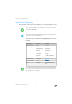
IP Settings 3.2 IP Settings The IP settings of the FRITZ!Box are preset upon delivery with the following values: Factory Settings All computers are located in the same IP network enabled IP address 192.168.178.1 Subnet mask 255.255.255.0 DHCP server enabled The IP address and the corresponding subnet mask yield the following values: Network address of the subnet 192.168.178.0 Entire IP address range for the computers 192.168.178.2 192.168.178.
IP Address 3.4 IP Address Upon delivery the FRITZ!Box is assigned the following IP address: 192.168.178.1 If you would like to change the IP address, please read through the following sections. Also note the additional information in the section “Reserved IP Addresses” on page 91. When Does It Make Sense to Change the IP Address? You should change the IP address of the FRITZ!Box if the following apply to your network: You have an existing local IP network, one subnet with several computers.
DHCP Server 3.5 DHCP Server The FRITZ!Box is equipped with its own DHCP server. The DHCP server is enabled by default in the factory settings. The following range of IP addresses is reserved for the DHCP server in the factory settings: 192.168.178.20 - 192.168.178.200 This IP address can be changed as needed. Every time the operating system on a computer connected with FRITZ!Box is started, the DHCP server assigns it an IP address from the IP address range of the DHCP server.
Disabling the DHCP Server Disabling the DHCP Server You can disable the DHCP server. To make sure that all computers remain in the same IP network as the FRITZ!Box, you must enter the IP addresses manually in the computers’ network settings. First disable the option “Obtain an IP address automatically” and then enter the IP address manually in the appropriate field. In the case of the preset IP address of the FRITZ!Box, the following IP addresses are available for assignment to the computers: 192.168.178.
Changing the Network Settings Factory Settings Upon delivery the interfaces of the FRITZ!Box are configured as follows: Interface IP Address Subnet mask DHCP server LAN 192.168.178.1 255.255.255.0 enabled WLAN 192.168.182.1 255.255.255.0 enabled Thus the following address pools are available to the DHCP server: Interface Address pool of the DHCP server at the interface LAN 192.168.178.20 - 192.168.178.200 WLAN 192.168.182.20 - 192.168.182.
Changing the Network Settings Here is how to change the network settings: 1. Select the “Advanced Settings / System / Network” menu in the “Settings” area. 2. Select the “IP Settings” tab. 3. Click the “IP Addresses” button. The “IP Settings” page is opened. 4. Once all desired changes to the settings have been configured, confirm by clicking “OK” to apply them.
More about Internet Telephony 4 More about Internet Telephony Voice over IP (VoIP) Internet telephony has already been in use for years, but today it allows even private customers the convenience familiar from conventional telephony, usually at significantly lower prices. Internet telephony has also made it considerably more convenient to use applications like conference calls and answering machines in networks.
Bandwidth Management 4.2 Bandwidth Management The FRITZ!Box is equipped with integrated bandwidth management. This function ensures that the speech quality during telephone calls over the Internet is not reduced by surfing activity. To do this, the FRITZ!Box adjusts all uploads and downloads to the currently available bandwidth. Because the FRITZ!Box also places a higher priority on Internet telephony connections over Internet data connections, unwelcome interference is largely avoided.
More Functions 5 More Functions This chapter introduces additional useful functions and features of the FRITZ!Box. 5.1 Night Service In the FRITZ!Box you can set up Night Service for WLAN and for the telephones connected to the FRITZ!Box. Configure Night Service in the “Settings” area, using the menu command “Advanced Settings / System / Night Service”. First define the period of time for which the Night Service of the FRITZ!Box should be active. For instance, from 10:00 p.m. to 6:00 a.m.
Alarm 5.2 Alarm The FRITZ!Box offers you the option of using connected telephones as alarm clocks. Configure the alarm function in the “Settings” area, using the menu command “Advanced Settings / Telephony / Alarm”. Enable the alarm function, enter the time and (if relevant) the day on which the alarm is to ring, and then select which telephone should ring at the specified time. As a final step, click the “Apply” button to save your settings in the FRITZ!Box.
Customer Service Guide 6 Customer Service Guide Help on All Important Service Topics AVM is there to help should any questions or problems arise. Here you will find the important information you need, in the form of manuals, updates and support. Microsoft Updates In many cases problems which arise during operation can be resolved by installing the current Microsoft Service Pack or other Microsoft updates.
information in the Internet 6.2 information in the Internet On its web site AVM presents comprehensive information on your AVM products as well as new product announcements and new product versions. Frequently Asked Questions (FAQs) We would like to make our products as easy to use as possible. If you still have problems, sometimes a little tip is all you need to resolve them. That is why we present you with a selection of frequently asked questions. The FAQs can be viewed at the following address: www.
Support from the Service Team 6.4 Support from the Service Team Should problems with your FRITZ!Box recommend taking the following steps: arise, we 1. If you have questions about starting operation of your FRITZ!Box, please consult the chapter “Connection” from page 12. 2. Please see the information in the section “Product Details” from page 70. 3. If you have any problems, seek first aid by consulting the chapter “Troubleshooting” from page 53.
Support by Fax Support by Fax If necessary, you can reach AVM Support at the fax number: +49 (0)30 / 39 97 62 66 The following information should be included in your fax to the Support team: Your name and address. An e-mail address or fax number at which you can be reached. the serial number of the FRITZ!Box The serial number is printed on the sticker attached to the base of the device. Support staff will always check this number to ensure that you are a registered user.
Glossary Glossary 802.11g++ Term for an accelerated variant of WLAN based on IEEE 802.11g. The 802.11g++ procedure functions as a kind of “turbo mode” for the IEEE 802.11g WLAN standard. By implementing special accelerations methods (frame bursting, packet aggregation), it increases the maximum gross transmission rate to 125 Mbit/s - as opposed to 54 Mbit/s for radio communication compliant with IEEE 802.11g.
Glossary ADSL2 offers range much greater than did the first ADSL generation, and is significantly more robust than ADSL, as it can simply disable single carrier frequencies when they produce interference. This feature allows ADSL2 to prevent synchronization losses. With a throughput rate of up to 12 Mbit/s downstream, ADSL2 offers considerably greater bandwidth than ADSL.
Glossary Default gateway DHCP see gateway abbreviation for Dynamic Host Configuration Protocol DHCP is a protocol for the dynamic negotiation of the operating parameters for the TCP/IP protocol (TCP is a transport protocol based on the Internet protocol). The computers of a local IP network (DHCP clients) access the DHCP server as part of their operating systems' start procedure.
Glossary This hierarchical system of DNS servers is known as the Domain Name System. The addresses of the DNS servers at which the Domain Name Service is to inquire by default generally are handed over to the computer by the Internet Service Provider automatically whenever a connection to the Internet is established. In local networks addresses can also be assigned via DHCP. Otherwise they must be entered manually in the TCP/IP settings of the computer by the user or the system administrator.
Glossary IP address. They are called dynamic because every participant receives a new public address that has not been assigned yet each time he or she dials in to the Internet. By contrast, dynamic addresses are usually used in local IP networks because they are easy to handle, and because using them avoids incorrect IP address entries or unintentional double assignments. The DHCP service is responsible for assigning unique dynamic IP addresses.
Glossary Fixed IP address Fixed IP addresses are IP addresses which are permanently assigned to a computer or another device like a network printer. Assigning fixed IP addresses makes sense in cases where a local network has a sufficiently large pool of IP addresses available, or when a computer is always supposed to be accessible at a certain address (such as a web server or e-mail server).
Glossary wishes to use the Internet connection. If the TCP/IP setting is configured by means of a DHCP server, there is no need to enter the gateway address manually. IP abbreviation for Internet Protocol The IP Internet Protocol is the most important basic protocol for the control of data exchange in local networks and in the Internet. The Internet protocol works without a connection; in other words, data packets are transmitted from the sender to the recipient without previous consultation.
Glossary is grouped into address classes designated as A, B, C, D and E. Only the first three of these five address classes are actually used.
Glossary the IP address determines the destination computer quite generally, the port addresses the communication interface provided by an application for a certain communication procedure. The Internet protocol allots 16 bits for the specification of the port number. Thus a total of 65,535 different port numbers can be specified. Ports up to port number 1,024 are reserved for special system applications and typical Internet applications.
Glossary pcAnywhere or Microsoft’s Remote Desktop, or even use of a file-sharing program like eDonkey, the required ports must be released for port forwarding. Port forwarding settings for the most important application cases are quite simple as long as the settings of the router or the firewall already contain rules with a corresponding preconfiguration. Private IP address Private IP addresses are used for computers and other network devices within local IP networks.
Glossary Subnetwork A local IP network can consist of one subnetwork or be divided into multiple subnetworks. The division into subnetworks is performed when the local IP network is configured. The subnetworks of a local IP network are also IP networks. Subnet mask The subnet mask indicates which part of an IP address is the network address and which the address of the computer. The network address defines what is called the subnet. Example 1 IP address: 192,168,178,247 Subnet mask: 255.255.255.
Glossary Example 2 IP address: 192.168.178.247 Subnet mask: 255.255.0.0 The assignment of the first two groups of numerals in the subnet mask indicates that the first two groups of numerals in the IP address define the network. The following addresses result: Network address of the subnet: 192.168.0.0 Address of the computer in the 192.168.178.247 subnet: IP address pool in the subnet: 192.168.0.0 192.168.255.255 That’s 65,536 IP addresses. The IP addresses 192.168.0.0 and 192.168.255.
Glossary device securely and automatically and thus, most importantly, facilitates simple initial configuration of the ADSL terminal equipment by the end customer. The TR-069 protocol can be used for automatic configuration only if it is actively supported by the given terminal device. For this an Auto Configuration Client (ACC) must be integrated in the device.
Glossary Today the UPnP forum specifies the UPnP standard and certifies devices that are compliant with the standard. VoIP abbreviation for Voice over IP, also known as Internet telephony Voice over IP makes telephone calls possible via the Internet. The technology has already been in use for years, but today it allows even private customers the convenience familiar from conventional telephony, usually at significantly lower prices.
Glossary WLAN abbreviation for Wireless LAN, or Wireless Local Area Network The term WLAN designates the industry standard for wireless local networks passed by the Institute of Electrical and Electronics Engineers (IEEE) in 1997 under the title IEEE 802.11. By means of WLAN technology, individual computers or network devices like printers or DSL access points can be linked wirelessly to an existing cable-connected local network (LAN), or LANs can be converted completely to a wireless structure.
Index Index A access rights user interface . . . . . . . . . . . . . . . . 23 alarm. . . . . . . . . . . . . . . . . . . . . . 31, 37 alternating between calls . . . . . . . . . 45 ambient conditions . . . . . . . . . . . . . . 74 analog telephone line . . . . . . . . . . . . 21 analog terminal equipment. . . . . . . . 22 answering machine connecting . . . . . . . . . . . . . . . . . . 22 setting up . . . . . . . . . . . . . . . . . . . 28 audio signals acknowledgement tone. . . . . . . . 32 autochannel .
Index E I ECT . . . . . . . . . . . . . . . . . . . . . . . . . . . 49 electrical power connecting . . . . . . . . . . . . . . . . . . 14 enable WLAN . . . . . . . . . . . . . . . . . . . . . . 36 error search . . . . . . . . . . . . . . . . . . . . 53 explicit call transfer . . . . . . . . . . . . . . 49 imprint . . . . . . . . . . . . . . . . . . . . . . . . . 2 information in the Internet. . . . . . . . 101 FAQs . . . . . . . . . . . . . . . . . . . . . . 101 installation . . . . . . . . . . . . . .
Index M R making internal calls . . . . . . . . . . . . . 43 recovery electrical equipment . . . . . . . . . . 76 electronic equipment. . . . . . . . . . 76 recycling . . . . . . . . . . . . . . . . . . . . . . . 76 repeater WDS. . . . . . . . . . . . . . . . . . . . . . . . 86 requirements for operation . . . . . . . . 11 room monitoring. . . . . . . . . . . . . . . . . 51 N network. . . . . . . . . . . . . . . . . . . . . . . . 89 connecting . . . . . . . . . . . . . . . . . . 15 factory settings . .
Index T W technical specifications . . . . . . . . . . 73 physical properties . . . . . . . . . . . 74 ports and interfaces . . . . . . . . . . 73 Telephone Book . . . . . . . . . . . . . . . . . 30 telephone connections . . . . . . . . . . . 27 configuring . . . . . . . . . . . . . . . . . . 27 telephony alarm . . . . . . . . . . . . . . . . . . . . . . 31 answering machine . . . . . . . . . . . 22 blocking calls . . . . . . . . . . . . . . . . 30 Call List. . . . . . . . . . . . . . . . . . . . .