
Operating instructions

6
2. Operation of the OVATION SA8.2
In the text you will find a number behind the names of the individual controls. These refer to the
numbering of the following drawings:
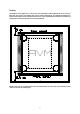
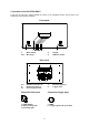
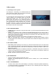
Front panel
1: Mains switch 2: Display
3a-e: Menu keys 4: DISPLAY switch
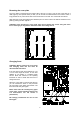
Rear panel
5, 6: Speaker connectors l/r 7: Balanced inputs l/r
8: RCA-Cinch inputs l/r 9: Trigger input
10: Power supply socket
Connection XLR-input Connection trigger input
1 = GND (Shield) a = GND
2 = Non inverting input b = Trigger signal (+2V up to +24V)
3 = Inverting input