
Data Sheet


AES-CELLIOT-AVT9152MOD
DATASHEET
The information in this document is subject to change without notice P a g e | 7
Rev 0.7.2 Sep 2020
Preliminary
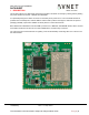
2.2. GPS Receiver Input Connector
A µ.FL conenctor (J1) is provided for user to connect to an external GPS antenna. J1 is connected to GPS receiver
input port of nRF9160.
The receiver supports GPS L1/CA reception. In Nordic’s white paper “nWP033- nRF9160 Antenna and RF
Interface Guidelines”, it is recommended to use active GPS antenna with LNA gain >15dB.
A 3V supply is provided to power external active GPS antenna via J1. It can be enabled via setting MAPGIO0 (pin
55 of nRF9160) to high. User may refer to “nRF91 AT Commands” for detail programming of this pin.
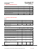
2.3. INTERCONNECTS BETWEEN nRF9160 AND nRF52840
Some interconnecting signals between nRF9160 and nRF52840 had been provided to aid communication/control
between the 2 devices.
nRF
9160
nRF
52840
GPIOs
nRF91_P0.17 nRF52_P0.15
nRF91_P0.18
nRF52_P0.17
nRF91_P0.19
nRF52_P0.20
LTE Modem Coexistence Interface
nRF91_COEX0 nRF52_P1.13
nRF91_COEX1 nRF52_P1.11
nRF91_COEX2
nRF52_P1.15
Sub
-
system Reset
nRF91_nRST nRF52_P0.13
nRF91_P0.27
nRF52_nRST
J1