Cyclades-PR2000 Installation Manual Access Router Cyclades Corporation
Cyclades-PR2000 Installation Manual Version 1.2 – May 2002 Copyright (C) Cyclades Corporation, 1998 - 2002 We believe the information in this manual is accurate and reliable. However, we assume no responsibility, financial or otherwise, for any consequences of the use of this Installation Manual.
Cyclades-PR2000 Table of Contents CHAPTER 1 HOW TO USE THIS MANUAL ........................................................................................................ 7 Installation Assumptions .................................................................................................................................... 8 Text Conventions ................................................................................................................................................ 8 Icons .......
Cyclades-PR2000 The IP Protocol................................................................................................................................................. 49 The Transparent Bridge Protocol ..................................................................................................................... 51 CHAPTER 8 DATA-LINK PROTOCOLS (ENCAPSULATION) ........................................................................... 52 PPP (The Point-to-Point Protocol) ...................
Cyclades-PR2000 Creation of user accounts and passwords ....................................................................................................... 87 IP Accounting ................................................................................................................................................... 89 CHAPTER 11 NAT (NETWORK ADDRESS TRANSLATION) .......................................................................... 90 Types of Address Translation ..............................
Cyclades-PR2000 Testing the WAN Interfaces ............................................................................................................................ 123 APPENDIX B HARDWARE SPECIFICATIONS ............................................................................................... 126 General Specifications ................................................................................................................................... 126 External Interfaces .........................
Cyclades-PR2000 CHAPTER 1 HOW TO USE THIS MANUAL Three Cyclades manuals are related to the PR2000. 1 The Quick Installation Manual -- provided with the router, 2 The Installation Manual -- available electronically on the Cyclades web site, 3 The CyROS Reference Guide -- also available electronically on the Cyclades web site. CyROS stands for the Cyclades Routing Operating System. It is the operating system for all Cyclades Power Routers (PR1000, PR2000, PR3000, and PR4000).
Cyclades-PR2000 Chapter 12 - Filters and Rules - demonstrates how to protect your router from undesired traffic. Chapter 13 - IPX - presents the hidden menus available only in routers with IPX activated. Chapter 14 - Virtual Private Network - describes CyROS’ VPN implementation. Appendix A - Troubleshooting - provides solutions and tests for typical problems. Appendix B - Hardware Specifications. Appendix C - Configuration Without a Console.
Cyclades-PR2000 Convention Description CONFIG=>INTERFACE=>L A combination of menu items, with the last being either a menu item, a parameter, or a command. In this example, L lists the interface configuration. A variable menu item that depends on hardware options or a choice of hardware or software options. IP Address A parameter or menu item referenced in text, without path prepended. Screen Text Screen Text , Simbols representing special keyboard keys.
Cyclades-PR2000 Cyclades Technical Support and Contact Information All Cyclades products include limited free technical support, software upgrades and manual updates. These updates and the latest product information are available at: http://www.cyclades.com ftp://ftp.cyclades.com/pub/cyclades Before contacting us for technical support on a configuration problem, please collect the information listed below. • • • • • • • • The Cyclades product name and model.
Cyclades-PR2000 The mailing address and general phone numbers for Cyclades Corporation are: Cyclades Corporation Phone: + 01 (510) 770-9727 Fax: + 01 (510) 770-0355 41829 Albrae Street Fremont, CA 94538 USA Chapter 1 - How to Use This Manual 11
Cyclades-PR2000 CHAPTER 2 WHAT IS IN THE BOX The Cyclades-PR2000 is accompanied by the following accessories: Back Panel of PR2000 Off On lug er P Pow t erne Eth WAN 1 h. nc Asy sole Con WAN 2 Cyclades - PR2000 DB-25 Male Power Cable Console Cable Labeled “Conf” DB-25 Male To Wall Outlet Gender Changer DB-25 DB-9 V.
Cyclades-PR2000 • • • • Quick Installation Manual Installation Manual & Reference Guide (on CD) Two straight-through cables Two V.35 Adapters Console Cable Mounting Kit Power Source & Cable Gender Changer • • • • Figure 2.1 shows which cables are used for each type of modem and how everything should be connected. The pinout diagrams of these cables are provided in Appendix B of the Installation Manual. The RJ-45 to DB25 adapter cable, which must be purchased separately, is shown in Figure 2.2.
Cyclades-PR2000 Chapter 3 Using CyROS Menus This chapter explains CyROS menu navigation and special keys. There are four ways to interact with CyROS: • Traditional menu interface using a console or Telnet session, • CyROS Management Utility based on interactive HTML pages, • SNMP (explained in the CyROS Reference Manual). Connection Using the Console Cable and a Computer or Terminal The first step is to connect a computer or terminal to the router using the console cable.
Cyclades-PR2000 Once the console connection is correctly established, a Cyclades banner and login prompt should appear on the terminal screen. If nothing appears, see the first section of the troubleshooting appendix for help. The second step is to log in. The preset super-user user ID is “super” and the corresponding preset password is “surt”. The password should be changed as soon as possible, as described in chapter 10 of the installation manual and at the end of every example in chapter 4.
Cyclades-PR2000 Special Keys or or or L These keys are used to end the input of a value. These keys are used to cancel a selection or return to the previous menu. In some isolated cases, this key jumps to the next menu in a series of menus at the same level. These keys have the expected effect of erasing previously typed characters. When available, this option displays the current configuration.
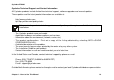
Cyclades-PR2000 The CyROS Management Utility After one of the interfaces has been connected and configured, there is another way to interact with CyROS. Type the IP address in the location field in an HTML browser of a PC connected locally or remotely through the configured interface. A super-user ID and password will be requested (these are the same ID and password used with the line-terminal interface). A clickable image of the router back panel will apear, as shown in Figure 3.2.
Cyclades-PR2000 The link Configuration Menu Interface will present an HTML version of the CyROS Main Menu, described previously. Clicking on an interface will show its current status and some additional information. Clicking on End HTTP Session will terminate the connection.
Cyclades-PR2000 CHAPTER 4 STEP-BY-STEP INSTRUCTIONS FOR COMMON APPLICATIONS This chapter provides detailed examples that can be used as models for similar applications. Turn to the example that is closest to your application, read the explanations, and fill in the blank spaces with parameters appropriate to your system. At the end of the section, you should have listed all the parameters needed to configure the router.
Cyclades-PR2000 STEP ONE The first step is to determine the parameters needed to configure the Ethernet interface (ETH0). The parameters in the Network Protocol Menu (IP) are shown in Figure 4.2. Fill in the blanks for your application in the right-most column. These parameters will be entered into the router later, after all parameters have been chosen. Each parameter in this menu is explained in more detail in chapter 5 of the Installation Manual.
Cyclades-PR2000 STEP TWO No more parameters are necessary for the Ethernet interface. The other interface to be configured is the SWAN. The SWAN physical media parameters are shown in Figure 4.3. Fill in the values for your application. The SWAN configuration is described in more detail in chapter 6 of the Installation Manual. Menu CONFIG=>INTERFACE=>SWAN=>PHYSICAL Parameter Example Mode Asynchronous Speed 38.4k Your Application FIGURE 4.
Cyclades-PR2000 Menu CONFIG=>INTERFACE=>SWAN=>NETWORK PROTOCOL=>IP Parameter Example Your Application Active or Inactive Active enables IP communication (IPX and Transparent Bridge are not used in this example). Interface Unnumbered/ Numbered Numbered Primary IP Address 0.0.0.0 (This number will be assigned by the Access Provider dynamically.) Subnet Mask 255.0.0.0 Secondary IP Address 0.0.0.0 for none IP MTU Use the preset value, 1500. This determines whether or not a given IP datagram is fragmented.
Cyclades-PR2000 STEP FOUR The Encapsulation parameters for PPP are less straight-forward. Many of them are based on decisions that cannot be shown in a diagram. Fortunately, the choices made here will mostly effect the performance of the link, rather than whether it works or not. Fill in the parameters appropriate for your system, consulting chapter 8 of the Installation Manual for more information if necessary.
Cyclades-PR2000 STEP FIVE A static route must be added to tell the router that all traffic not intended for the local LAN should be sent to the Access Provider. Chapter 9 of the Installation Manual explains static routes and other routing methods available in CyROS. Fill in the spaces in Figure 4.6 with the values for your application. Menu CONFIG=>STATIC ROUTES=>IP=>ADD ROUTE Parameter Example Destination IP Address Type in the word "DEFAULT".
Cyclades-PR2000 STEP SEVEN NAT parameters will now be determined for routing outside of the local LAN. Network Address Translation maps the local IP addresses, registered in the local address range menu below, to the one global IP address assigned by the access provider. Local IP addresses not indicated in this menu will be discarded. Menu CONFIG =>SECURITY =>NAT =>LOCAL ADDRESS =>ADD RANGE Parameter Example Your Application First IP Address 192.168.0.10 Last IP Address 192.168.0.30 FIGURE 4.
Cyclades-PR2000 Instructions for creating a backup of the configuration file. Use the menu option ADMIN =>WRITE CONFIGURATION =>TO FTP SERVER. Fill in the IP address of the computer where the configuration file should be saved, the file name, the directory name, and the user account information. This configuration file can later be downloaded with the ADMIN =>LOAD CONFIGURATION =>FTP SERVER option. Instructions for listing the configuration.
Cyclades-PR2000 Example 2 A LAN-to-LAN Example Using Frame Relay This section will guide you through a complete router installation for the connection of two LANs via Frame Relay. Figure 4.9 shows the example system used in this section. Spaces have been provided next to the parameters needed for the configuration where you can fill in the parameters for your system. Do this now before continuing. Central Office's LAN Network IP: 100.130.130.0 ________ Mask: 255.255.255.0 ________ ETH0 PR2000 100.130.
Cyclades-PR2000 STEP ONE The first step is to determine the parameters needed to configure the Ethernet interface (ETH0). The parameters in the Network Protocol Menu (IP) are shown in Figure 4.10. Fill in the blanks for your application in the right-most column. These parameters will be entered into the router later, after all parameters have been chosen. Each parameter in this menu is explained in more detail in chapter 5 of the Installation Manual.
Cyclades-PR2000 STEP TWO No more parameters are necessary for the Ethernet interface. The other interface to be configured is the SWAN in slot 1. The SWAN physical media parameters are shown in Figure 4.11. Fill in the values for your application. The SWAN configuration is described in more detail in chapter 6 of the Installation Manual. Menu CONFIG=>INTERFACE=>SWAN=>PHYSICAL Parameter Example Your Application Mode Synchronous.
Cyclades-PR2000 STEP THREE The network protocol parameters, shown in Figure 4.12, are similar to those for the Ethernet interface. Fill in the parameters for your network in the right-most column. Menu CONFIG=>INTERFACE=>SWAN=>NETWORK PROTOCOL=>IP Parameter Example Your Application Active or Inactive Active enables IP communication (IPX and Transparent Bridge are not used in this example). Interface Unnumbered/ Numbered Numbered Primary IP Address 200.240.230.2 Subnet Mask 255.255.255.
Cyclades-PR2000 STEP FOUR The Encapsulation parameters for Frame Relay are less straight-forward. Many of them are based on decisions that cannot be shown in a diagram. Fortunately, the choices made here will mostly effect the performance of the link, rather than whether it works or not. Fill in the parameters appropriate for your system, consulting chapter 8 of the Installation Manual for more information if necessary.
Cyclades-PR2000 Menu CONFIG=>INTERFACE=>SWAN=>ENCAPSULATION=>FRAME RELAY=>=>ADD DLCI Parameter Example Your Application DLCI Number Sixteen. This number is supplied by the Public Frame Relay network provider. Frame Relay Address Map Static, which maps one IP address to this DLCI. IP Address 200.240.230.1 Enable Predictor Yes, if Cyclades routers are used on both Compression ends of the link and Predictor Compression is enabled on both routers.
Cyclades-PR2000 Menu CONFIG=>STATIC ROUTES=>IP=>ADD ROUTE Parameter Example Destination IP Address 15.0.0.0 Subnet Mask 255.255.255.0 Gateway or Interface gateway Gateway IP Address 200.240.230.1 Metric One -- number of routers between router being configured and the destination IP address. Is This a Backup Route? No OSPF Advertises This No Static Route Your Application FIGURE 4.
Cyclades-PR2000 Instructions for creating a backup of the configuration file. Use the menu option ADMIN =>WRITE CONFIGURATION =>TO FTP SERVER. Fill in the IP address of the computer where the configuration file should be saved, the file name, the directory name, and the user account information. This configuration file can later be downloaded with the ADMIN =>LOAD CONFIGURATION =>FTP SERVER option. Instructions for listing the configuration.
Cyclades-PR2000 Example 3 Link Backup This example shows the configuration of a backup link, with a swan connection to a public Frame Relay Network providing the primary link and a SWAN with a PPP connection providing the secondary link. Figure 4.16 shows the networks used in this example. It is assumed that the routers are already connected to LANs and that the SWAN interfaces have already been configured and are working.
Cyclades-PR2000 STEP ONE The bandwidth used by CyROS for multilink circuit calculations is that given in the traffic control menu, rather than the actual physical bandwidth available. If this bandwidth value is not set, the preset value (zero) will be used and the multilink circuit will not function. The bandwidth for both links (SWAN 1 and SWAN 2 in the example) should also have been set when the interface was configured. If not, the multilink circuit will not work.
Cyclades-PR2000 Menu CONFIG=>MULTILINK=>MULTILINK CIRCUIT NUMBER=>ADD/MODIFY INTERFACE Parameter Example Your Application Slot N SWAN 1 Type of Interface Main Time to Activate 5 Backup After This Link Goes Down Time to Deactivate 20 Backup After This Link Returns FIGURE 4.18 ADDITION OF THE PRIMARY (MAIN) LINK Menu CONFIG=>MULTILINK=>MULTILINK CIRCUIT NUMBER=>ADD/MODIFY INTERFACE Parameter Example Your Application Slot N SWAN 2 Type of Interface Backup Time to Activate Zero, since this link IS the backup.
Cyclades-PR2000 STEP THREE Up to this point, the configuration can be used either for link back up or for load back up. This example shows link back up, but parameters applicable to load back up will be mentioned when they appear. Complete information on the multilink circuit concept is provided in chapter 4 of the CyROS Reference Guide. Menu CONFIG=>MULTILINK=>MULTILINK CIRCUIT NUMBER=>CIRCUIT ATTRIBUTES Parameter Example Your Application Criterion for Traffic This parameter has no effect for link backup.
Cyclades-PR2000 STEP FOUR Now, a static backup route must be created for the secondary link. It is assumed that a route of some sort (static, RIP, etc.) already exists for the primary link. The static route parameters for the example secondary link are shown in Figure 4.21. Fill in the parameters for your system. Menu CONFIG=>STATIC ROUTES=>IP=>ADD ROUTE Parameter Example Destination IP Address 200.206.206.0 Subnet Mask 255.255.255.0 Gateway or Interface Gateway Gateway IP Address 100.200.200.
Cyclades-PR2000 STEP SIX The multilink circuit can be tested by temporarily deactivating the interface on the primary link. This is done in the ADMIN=> START/STOP INTERFACE menu by selecting the SWAN interface. If there is traffic, the backup link should then take over, and the menu item INFO =>SHOW ROUTING TABLE will show that the backup link is working. (To create traffic, try pinging a host in the destination network.
Cyclades-PR2000 CHAPTER 5 CONFIGURATION OF THE ETHERNET INTERFACE The PR2000 has one Ethernet 10Base-T interface, provided in a standard RJ-45 modular jack, which should be connected to an Ethernet hub or switch. Use a standard 10Base-T straight-through cable (not included). When the Ethernet link is correctly connected, the link LED will be lit. The menus for the Ethernet Interface are independent of the speed of the link.
Cyclades-PR2000 Network Protocol Menu (Continued) Parameter Description Secondary IP Applies to Numbered interfaces. Indicates a second (or third, etc. up to eight) IP Address address that can be used to refer to this interface. This parameter and the next are repeated until no value is entered. Subnet Mask Applies to Numbered interfaces. Subnet mask of Secondary IP Address. IP MTU Assigns the size of the Maximum Transmission Unit for the interface.
Cyclades-PR2000 IP Bridge An IP Bridge is used to divide a network without subnetting. Whenever a subnetwork is created, two IP numbers are lost — one describing the network and the other reserved for broadcast. This does not occur with an IP Bridge. 200.240.240.9 200.240.240.3 200.240.240.2 200.240.240.1 ETH0 PR2000 Link 1 PR3000 ........ ........ ........ ........ .. ETH0 200.240.240.8 200.240.240.4 FIGURE 5.1 IP BRIDGE EXAMPLE In Figure 5.1, an example of the use of an IP Bridge is given.
Cyclades-PR2000 Network Protocol Menu (Continued) -- (IP Bridge) Parameter Description IP Bridge Activates the IP Bridge functionality. The following parameters apply only if IP Bridge is Active. Initial IP Address to Indicates the start of the range of IP addresses to be transferred to another physical be Bridged location. This and the next three parameters are repeated in case the bridge is to be broken up into various sections. Up to 8 sections can be defined. In the example, this value is 200.240.240.
Cyclades-PR2000 CHAPTER 6 THE SWAN AND ASYNC INTERFACES This chapter describes how to configure a SWAN interface. The physical link should be set up as shown in chapter 2, according to the type of modem or device at the other end of the connection and the type of SWAN port. The async interface, provided on an RJ-45 connector, is the same as the SWAN interface except that the synchronous option does not appear in the CONFIG =>INTERFACE =>SWAN =>PHYSICAL menu and the only encapsulation option is PPP.
Cyclades-PR2000 STEP TWO The second step is to choose a data-link protocol in the Encapsulation Menu. There are many encapsulation options on this interface. For synchronous communication: • Frame Relay: the Frame Relay Protocol is based on frame switching and constructs a permanent virtual circuit (PVC) between two or more points. • X.25: The X.25 Protocol is generally used to connect to a public network. The router can act either as a DTE or a DCE. • HDLC: A proprietary alternative to PPP.
Cyclades-PR2000 STEP FOUR If PPP Encapsulation is being used, a type of authentication should be chosen. This is done in the authentication menu. Authentication Menu CONFIG=>INTERFACE=>SWAN=>AUTHENTICATION Parameter Authentication Type Description Local uses the list of users defined in CONFIG=> SECURITY=>USERS=>ADD. Server uses either Radius or Tacacs to authenticate the user.
Cyclades-PR2000 CHAPTER 7 NETWORK PROTOCOLS The second step in most interface configurations is to choose which network protocol to use and assign values to the relevant parameters. At least one of IP, Transparent Bridge, or IPX (optional, and discussed in chapter 13) must be activated. Use the information provided below to set the parameters for each interface. The Ethernet network protocol menu includes IP bridging and is explained in chapter 5. The SWAN Network Protocol Menu is given in figure 7.1.
Cyclades-PR2000 The IP Protocol If the preset values provided by the operating system are accepted, the interface will work at a basic level. The most common options are explained in the following table. Network Protocol (IP) Menu CONFIG=>INTERFACE=>=>NETWORK PROTOCOL=>IP Parameter Active or Inactive Interface Unnumbered Assign IP From Interface Description Activates this interface. Unnumbered interfaces can be used for point-to-point connections. Applies to Unnumbered interfaces.
Cyclades-PR2000 Network Protocol (IP) Menu (Continued) Parameter IP MTU Description Assigns the size of the Maximum Transmission Unit for the interface. This determines whether or not a given IP datagram is fragmented. NAT Determines the type of IP address if NAT is being used. Use Global otherwise. See chapter 13 or the examples in chapter 4 for details on how to configure NAT.
Cyclades-PR2000 The Transparent Bridge Protocol The Transparent Bridge Protocol can be used in conjunction with either IP or IPX. A detailed explanation of its use appears in section 4.6 of the CyROS Reference Guide. Transparent Bridge Menu CONFIG=>INTERFACE=>SWAN=>NETWORK PROTOCOL=>TRANSPARENT BRIDGE Parameter Status Port Priority Description Activates the Transparent Bridge on this interface.
Cyclades-PR2000 CHAPTER 8 DATA-LINK PROTOCOLS (ENCAPSULATION) Each encapsulation option is presented in a separate section in this chapter. Not all data-link protocols are available for all interfaces. PPP (The Point-to-Point Protocol) PPP is the only encapsulation option than can be either synchronous or asynchronous. It is important to choose between them in CONFIG =>INTERFACE => =>PHYSICAL before entering the Encapsulation menu. The menu options depend on this choice.
Cyclades-PR2000 PPP Menu (Continued) Parameter Disable LCP Echo Requests Description LCP (Link Control Protocol) messages are normally exchanged to monitor the status of the link. Disabling these messages reduces traffic, but the link then has no way of knowing if the other end is still connected. Time Interval to Send Config Request messages are used to negotiate the parameters at the start of a PPP Config Requests connection.
Cyclades-PR2000 CHAR The configuration of the CHAR data-link protocol is confined to one menu, CONFIG =>INTERFACE => =>ENCAPSULATION =>CHAR. Information about all the parameters appearing in this menu is provided in the table below. Not all parameters will appear for all interfaces. CHAR Encapsulation Menu CONFIG=>INTERFACE =>=>ENCAPSULATION =>CHAR Parameter Device Type Description Determines whether a Terminal, Printer, or Socket device will be connected to this port.
Cyclades-PR2000 PPPCHAR The configuration of the PPPCHAR protocol is contained in the menu CONFIG =>INTERFACE => =>ENCAPSULATION =>PPPCHAR. The parameters for PPPCHAR are a combination of those for PPP and CHAR. See the tables describing the PPP and CHAR options for guidance in configuring this protocol. HDLC This data-link protocol is a proprietary alternative to PPP. It has only one parameter, the HDLC Keepalive Interval. This is the time interval between transmission of Keepalive messages.
Cyclades-PR2000 The Local Management Interface (LMI) Protocol provides services not available in simple Frame Relay. It is used for controlling the connection between the user and the network. It monitors this link, maintains the list of DLCs, and sends status messages about the PVCs. A separate virtual circuit is created to pass this information (DLCI 0).
Cyclades-PR2000 STEP TWO After configuring the general parameters, each DLC must be defined. An example will be used to demonstrate the procedure. A public Frame Relay network connecting offices in São Paulo, Rio de Janeiro, Salvador, and Recife is shown in Figure 11.1. Each router will have a routing table pairing destination network with router interface and gateway. A Frame Relay Address Map is also created (either statically or dynamically) to associate each DLCI with the destination router IP.
Cyclades-PR2000 São Paulo Network: 192.168.200.0 Rio de Janeiro Network: 192.168.201.0 Router Router 200.1.1.1 200.1.1.4 21 11 81 200.1.1.2 Router Salvador Network: 192.168.203.0 200.1.1.3 Router Recife Network: 192.168.202.0 FIGURE 8.
Cyclades-PR2000 Add DLCI Menu CONFIG=>INTERFACE => =>ENCAPS =>FRAME RELAY => =>ADD DLCI Parameter DLCI Number Description Used to identify the DLC. This number is supplied by the Public Frame Relay network provider. The DLCIs are stored in a table which can be seen with the L command. Frame Relay Address Determines the method used for mapping the remote IP address to the Permanent Map Virtual Circuit. Static maps one IP address to this DLCI.
Cyclades-PR2000 Modem or DSU/CSU Router / DTE Router / DTE Switch / DCE Switch / DCE X.25 FIGURE 8.2 PUBLIC X.25 NETWORK EXAMPLE X.25 A Cyclades Router can act either as a DTE (Data-terminal Equipment) connected to a public X.25 network or as a DTE or DCE (Data circuit-terminating Equipment) as part of a private X.25 network. The first case is discussed in this chapter. The second case is described in the CyROS Reference Guide.
Cyclades-PR2000 X.25 Menu CONFIG=>INTERFACE=>=>ENCAPSULATION =>X.25 Parameter Description X.121 (Local DTE) Address Address assigned to this interface (provided by the public X.25 Network Provider). Can be up to 15 digits. Switch Mode Active Causes the Router to act as a switch. Incoming Calls Received Applies when Switch Mode is Active. Over the Other X.25 Links With Unknown Destination DTE Can be Forwarded Through This Link Suppress Calling Address Public X.
Cyclades-PR2000 X.25 Menu (Continued) Parameter Packet Size Number of Retries N2 TL T2 T21 T23 Negotiable Facilities Send Facility Description The packet size to be sent across the interface. This number may be negotiated if the Packet Size Facility is utilized (see last parameter in this table). Number of times an information frame can be resent, without response, before the link is considered down. Time the frame level waits for an acknowledgement for a given frame before resending it.
Cyclades-PR2000 STEP TWO The next step is to create a static routing table associating each remote X.121 address with an IP address or a TCP Socket location. This is done in the Add DTE menu, which appears at the end of the X.25 parameter list. It can be reached by passing through all X.25 parameters or by using the key at any point in the parameter list. X.25 Add DTE Menu CONFIG=>INTERFACE=>=>ENCAPSULATION =>X.
Cyclades-PR2000 CHAPTER 9 ROUTING PROTOCOLS Routing Strategies Routing can be done either statically or dynamically. Static Routing Static routing is recommended when the network contains a small number of routers and other equipment. When a system is simple and without redundant links, static routing is the simplest option. Even with some redundant links, a multilink circuit can be created for semi-dynamic routing behavior. Multilink circuits are described in section 4.4 of the CyROS Reference Guide.
Cyclades-PR2000 Static Routes Routers used in very small or simple networks may use static routes as the primary routing method. When RIP or OSPF are used, some static routes may still be needed. Configuration of static routes will be explained using two examples. Network 2 142.10.0.0 Mask: 255.255.0.0 D 142.10.0.4 142.10.0.2 C 142.10.0.1 142.10.0.3 Router 2 192.168.100.1 192.168.100.0 Mask: 255.255.255.0 Router 1 10.0.0.3 F E 10.0.0.0 Mask: 255.0.0.0 B A 10.0.0.1 192.168.100.2 192.168.100.
Cyclades-PR2000 Router 2 Unnumbered Interfaces int -Po n ctio Slot 3 ETH0 192.168.100.1 ne Con t-to Poin Slot 1 Router 1 ETH0 F 10.0.0.3 E Network 3 B A Network 1 FIGURE 9.2 STATIC ROUTING EXAMPLE 2 Figure 9.2 shows another static routing example to explain the Gateway or Interface parameter. Between the two routers is a point-to-point connection. Another network could be created, but is not necessary.
Cyclades-PR2000 Add Static Route Menu CONFIG =>STATIC ROUTES =>IP =>ADD ROUTE Parameter Destination IP Address Subnet Mask Gateway or Interface Gateway IP Address Interface Metric Is This a Backup Route? OSPF Advertises This Static Route External Metric External Metric-Type Description Address that route will lead to. To configure a default route, type "default" for this parameter, otherwise enter 0.0.0.0 in both this and the next parameter.
Cyclades-PR2000 RIP Configuration CyROS supports three basic types of RIP: 1 RIP1 [RFC 1058] 2 RIP2 with broadcast (compatible with RIP1) [RFC 1723] 3 RIP2 with multicast [RFC 1723] The primary difference between RIP1 and RIP2 is that only RIP2 advertises subnet masks and next hops. If the network contains equipment that understands only RIP1 packets, then RIP1 or RIP2 with broadcast should be used. See RFC 1723, item 3.3 for more details. If only RIP2 is used, RIP2 with multicast is recommended.
Cyclades-PR2000 OSPF The OSPF (Open Shortest Path First) routing protocol is significantly more complicated than RIP. The determination of which protocol is better suited to a given network is beyond the scope of this manual. An example network using OSPF is given in Figure 9.3.
Cyclades-PR2000 First, some definitions: • An Autonomous System (AS) is a portion of the network that will use a single routing strategy. It is made up of a backbone area and optionally of non-backbone areas. • OSPF Areas are sub-systems that have identical routing databases. An area generally has no knowledge of the routing databases of other areas. • The Backbone connects areas and contains any routers not contained in another area.
Cyclades-PR2000 OSPF Menu (continued) External Metric Defines the metric that will be advertised by OSPF. External Metric Type For Type 1, the total metric of this route is composed of the internal metric (inside the autonomous system) and the external metric (provided in the previous parameter). For Type 2, the total metric of this route is the value provided in the previous parameter. Parameters that apply only when OSPF on This Interface is Enable or Enable Inactive.
Cyclades-PR2000 OSPF Global Configurations STEP THREE After completing the OSPF interface configuration for all interfaces (even those that will not use OSPF), navigate to the OSPF Menu, CONFIG=>IP=>OSPF. Enter into the OSPF Global Commands menu and set the parameters as indicated in the table below. OSPF Global Commands Menu CONFIG =>IP =>OSPF =>GLOBAL Parameter OSPF Protocol Router ID Description Enables OSPF on all interfaces. Assigns a unique ID to the router for use by the OSPF protocol.
Cyclades-PR2000 OSPF Global Commands (Continued) Parameter RIP External MetricType Advertise Non-OSPF interfaces Advertise Static Routes Description Applies when Advertise RIP routes is set to Yes. For Type 1, the total metric of this route is composed of the internal metric (inside the autonomous system) and the external metric (provided in the previous parameter). For Type 2, the total metric of this route is the value provided in the previous parameter.
Cyclades-PR2000 Area Menu (continued) Area Range N Status An Area Border Router (ABR) advertises link states for all networks within the area. The number of such advertisements can potentially be reduced by condensing different IP networks into a single range. Area Range N Net Applies when Area Range N Status is Active. Address Sets the network IP address for the range. Area Range N Mask Applies when Area Range N Status is Active. Sets the network IP mask for the range.
Cyclades-PR2000 STEP SIX It is not always possible to connect all areas directly to the backbone. When an area is connected to the backbone only through another area, two virtual links must be created. One from the backbone to the unattached area and one from the unattached area to the backbone. If this occurs in the network containing the router, enter the Virtual Links Menu to configure this link.
Cyclades-PR2000 BGP-4 Configuration The BGP-4 routing protocol is used for routing on the Internet, performed between Autonomous Systems (ASs). An autonomous system is defined as: · A set of routers and networks under the same administration. · An interconnected network, where no router is reachable solely through a path exterior to the AS Each AS is identified by a 16-bit AS number. This number is supplied by the service provider. Steps 1. Complete the Global Parameters 2.
Cyclades-PR2000 The last option is to aggregate the addresses contained in the local autonomous system in order to present an aggregated route to the outside world. This is done in the last step. 8. Aggregate the addresses contained in the AS. The steps defined above will now be clarified. STEP ONE The global parameters apply to the router’s AS. Classless Inter-Domain Routing (CIDR) Address notation is used instead of the normal IP Address and Subnet mask notation. Both are shown in Figure 9.4.
Cyclades-PR2000 CONFIG=>IP=>BGP4=>GLOBAL Parameter BGP4 Protocol Local AS Number Router Identifier Cluster Identifier Default Local Preference Accept Connections From All Peers Advertise Direct Routes Description Activates the protocol. This number is assigned by the service provider. Usually the same as the Router ID, one of the interface IP addresses Only used when this router is used as a router reflector. Value of the attribute "local pref" used by IBGP.
Cyclades-PR2000 STEP TWO The neighbor menu identifies the routers inside and outside the AS that will communicate with the router via BGP4. Each update message exchanged between routers contains path attributes. How these path attributes are manipulated by the router when routes are received or sent to each neighbor is determined here. CONFIG=>IP=>BGP4=>NEIGHBOR=>ADD Parameter Name Description A string to facilitate identification of the Neighbor.
Cyclades-PR2000 CONFIG=>IP=>BGP4=>NEIGHBOR=>ADD (continued) Keepalive Connection Retry Time Start Time Incoming Distribution Access List Name Outgoing Distribute Access List Name Incoming Filter Access List Name Outgoing Filter Access List Name Incoming Community Access List Name Outgoing Community Access List Name Incoming Route Map Number Outgoing Route Map Number Neighbor Alias Address Interval between keepalive messages sent to this neighbor.
Cyclades-PR2000 esired Route Und 2 3 1 PR3000 ..... ..... ..... .... ..... ..... ..... 4 Pr e f er red Route 6 Bac 5 100.10.0.0/16 kup Route FIGURE 9.5 MULTIPLE ROUTES CONTAINING AS 5 CONFIG=>IP=>BGP4=>ACCESS LIST=>ADD Parameter Access List Name Access List Type Rule Status Default Scope Description Name assigned to list, to indicate which interface and direction it applies to.
Cyclades-PR2000 STEP FOUR An access list needs at least one rule. The example in Figure 9.6 shows three access lists, each one with several rules. Each neighbor can be assigned up to 6 access lists, as seen in step 2. Discarded Routes Discarded Routes Discarded Routes Rule 0 Rule 1 Access list popeye_dist type Distribution Rule 2 Rule 0 Rule 1 Access list popeye_comm type Community Rule 2 Rule 0 Route Map Rule 1 Seq. 2 Seq. 4 Seq.
Cyclades-PR2000 CONFIG=>IP=>BGP4=>ACCESS LIST=>CONFIGURE RULES=>=>ADD Parameter Rule Status Scope Rule AS Position Rule AS Number Rule Distr. Search Type Rule Distr. Address Rule Distr. Mask Bitlen Community Description Enables the rule. See explanation of this parameter in step 3. Applies only for Access List Type equal to AS Path. Limits the search on AS number to a particular position in the route. For the example in Figure 12.
Cyclades-PR2000 STEP SIX A route map can either apply to all routes not discarded by the access lists, as shown in Figure 9.6, or to routes filtered by a particular access list, as shown in Figure 9.7. Discarded Routes Discarded Routes Rule 1 Rule 0 Rule 2 Rule 0 Rule 1 Rule 1 Rule 0 Rule 2 Seq. 4 Seq. 2 Seq. 10 BGP-4 Message From Tele Popeye Access list popeye_comm type Community Access list popeye_path type AS Path Access list popeye_dist type Distribution Route Map FIGURE 9.
Cyclades-PR2000 CONFIG=>IP=>BGP4=>ROUTE MAP=>ADD Parameter Route Map Number Sequence Number Match List Name Weight Origin, Set Nexthop, Set Metric, Set Local Preference, Set Atomic Aggregate, Set Aggregate AS number, Set AS Path, AS Path Prepend, AS Path AS-SET Description Identifies the route map Identifies the sequence within the route map. The numbers need not be consecutive. Associates an access list with this sequence, as shown in the figure above. Alters the weight used to determine the best path.
Cyclades-PR2000 CONFIG=>IP=>BGP4=>AGGREGATE ADDRESSES=>ADD Parameter Number Address Mask (bitlen) AS Set Summary Only Description An ID for reference. The aggregated address. In the example, 200.50.50.0. The mask for the aggregated address. In the example, 23. Yes causes the route to be tagged with the AS Set path attribute. Otherwise, the AS Sequence path attribute is assigned. Yes removes all more specific routes, leaving only the aggregated form. No maintains both the individual and aggregated routes.
Cyclades-PR2000 CHAPTER 10 CYROS, THE OPERATING SYSTEM This chapter explains various operating system features that are not covered in other chapters: • creation of the host table • creation of user accounts and passwords • IP Accounting Creation of the host table CyROS allows identification of hosts by name. In the menu CONFIG =>SYSTEM=>HOSTS, each host is assigned a number (1 to 32), and a host name (a maximum of 8 characters).
Cyclades-PR2000 Other users can be created and the user “usr” can be assigned a password. The password of the super user should be changed as soon as possible. The menu CONFIG=>SECURITY=>USERS allows addition, deletion, and modification of the list of users. The parameters are: • • • • • • User Name, Password, User Type: Super, Usr, Auto, or PPPAuto, User Status: Disabled or Enabled, Hosts 1 through 4 (the host names entered here must already exist in the host table).
Cyclades-PR2000 login name is indicated when the auto user is configured, the user is logged in to the remote host directly (though a password may be necessary, depending on the remote host configuration). IP Accounting IP Accounting is used to count the total number of packets allowed (or not) to pass through an interface. Statistics are given for packets that meet the criterions defined in a rule. (Traffic Rules are not supported).
Cyclades-PR2000 CHAPTER 11 NAT (NETWORK ADDRESS TRANSLATION) NAT exists to convert local IP addresses into Internet “global” IP addresses. Internet IP addresses are assigned by Internet providers. Due to the explosion of the internet, these numbers are scarce. Certain ranges of IP addresses are reserved for internal use only — they may not have a direct connection to the Internet (for reference, they are 10.0.0.0 - 10.255.255.255, 172.16.0.0 - 172.16.255.255, and 192.168.0.0 192.168.255.255).
Cyclades-PR2000 There are two types of NAT available in CyROS -- Normal NAT and Expanded NAT. This chapter describes Expanded NAT. A description of Normal NAT appears in Chapter 4 of the CyROS Reference Guide. What is the difference between Expanded and Normal Mode NAT? The Normal Mode is a previous implementation of NAT used in the Power Router line. It has been maintained for backward compatibility.
Cyclades-PR2000 NAT Static Translation Table # 1 2 3 Global address 200.240.230.225 200.240.230.225 200.240.230.225 / / / / port 20 21 80 local address 192.168.0.30 192.168.0.30 192.168.0.31 / / / / Port 20 21 80 Protocol TPC TPC TPC Types of Address Translation In dynamic address translation, a pool of global IP addresses is loosely related to a pool of local IP addresses.
Cyclades-PR2000 An overview of the NAT menu is shown in the table below. NAT Menu CONFIG =>SECURITY =>NAT Menu Option General Global Address Local Address Static Translation Timeout Description Parameters for enabling NAT and choosing the NAT Mode. Also includes port translation option. The first and last IP addresses in the range. In the example, these numbers are 200.240.230.225 and 200.240.230.238. The local network IP address and network mask, and whether or not the network should be translated.
Cyclades-PR2000 STEP TWO The parameters in the Timeout Menu are explained in more detail below. The preset values should be appropriate for most applications. Timeout and Options Menu CONFIG =>SECURITY =>NAT =>TIMEOUT AND OPTIONS Parameter UDP Timeout Description Inactivity time required before a UDP translation is removed from the translation table. An entry is created in the translation table the first time a UDP packet passes through the interface. Five minutes is a reasonable time.
Cyclades-PR2000 STEP FOUR If static translations are to be performed, as described in the example, the parameters in the Static Translation Menu must be set. A brief explanation of each parameter is given in the table. Static Translation Menu CONFIG =>SECURITY =>NAT =>STATIC TRANSLATION => ADD ENTRY Parameter Global IP Address Protocol Global Port Local IP Address Local Port Description One of the addresses assigned by the Internet access provider and included in one of the NAT global address ranges.
Cyclades-PR2000 CHAPTER 12 RULES AND FILTERS There are four basic types of rules: 1 IP filter rules, 2 Radius rules (actually a combination of previously defined IP filter rules), 3 traffic control rules, and 4 transparent bridge rules (similar to IP filter rules, but for applications that use a transparent bridge). IP filter rules and traffic control rules will be covered in detail in this chapter. See section 4.7 of the CyROS Reference Guide for more information about all four types of rules.
Cyclades-PR2000 Config Rules List IP Add Rule List Edit Rule List Configure Rules Clear Rule List Rule List Name Rule Status Rule List Type Default Scope Same as Add Incoming Rule List Name Rule List Outgoing Rule List Name Linked Rule List Name N Rule List Name Insert as Rule Number Rule Status Add Rule Scope Rule Priority Level Reserved Bandwidth Bandwidth Priority Level Protocol Source IP Operator IP Address Start Mask IP Address Start IP Address End Destination IP Operator IP Address Start Mask I
Cyclades-PR2000 Exterior Router Slot 1 Perimeter Network 192.168.0.0 ETH0 192.168.0.2 192.168.0.1 Slot 1 Interior Router Router 172.16.0.0 192.168.0.3 ETH0 Bastion Host 10.0.0.0 Extension to Network FIGURE 12.2 FIREWALL EXAMPLE Figure 12.2 will be used to show how both an exterior router and an interior router would be configured using the filters available in CyROS.
Cyclades-PR2000 Exterior Router The exterior router is the network’s first defense against attacks. For this reason, it is reasonable to prohibit all packets except for those explicitly allowed. This is done by choosing the Default Scope to be Deny. Thus, ALL desired traffic must be expressly allowed by the rules in the rule list. World of Po ss ib P le DENY ets Let e-mail out Let e-mail in ac k DENY DENY Let Telnet Connections Out FIGURE 12.3 DENY AS DEFAULT SCOPE In Figure 12.
Cyclades-PR2000 Steps necessary to activate filtering on the exterior router in the example: 1 There are two interfaces with two directions each. Filtering on link 1 requires the creation of two rule lists, called exterior_in and exterior_out. Create them using the menu CONFIG =>RULES LIST =>IP =>ADD RULE LIST and the following parameters: Rule List Type = Filter Default Scope = Deny Linked Rule List Name = None 2 Create the rules for each rule list in the order in which they should be evaluated.
Cyclades-PR2000 The configuration for “Let e-mail in” is shown in the following figure (obtained by selecting CONFIG =>RULES LIST =>IP =>L in the menus): Rules Lists Rule List Name Rule Status Default Scope List Type exterior_in exterior_out Deny Deny Filter Filter Enabled Enabled Linked Rule List Filter_list Name exterior_in Rule 0 Status Enabled Scope Permit Protocol TCP Source IP Operator None Destination IP Operator Equal Destination IP start 192.168.0.3 Destination IP Mask 255.255.255.
Cyclades-PR2000 Filter_list Name exterior_out Rule 0 Status Enabled Scope Permit Protocol TCP Source IP Operator Equal Source IP start 192.168.0.3 Source IP Mask 255.255.255.255 Destination IP Operator None Source Port Operator Equal Source Port Start SMTP Destination Port Greater than Operator Destination Port Start 1023 TCP connections allowed N Account Process allowed N FIGURE 12.
Cyclades-PR2000 Interior Router If an interior router exists in the network, the administrator may decide to use a Default Scope of Permit. In this case, all undesired traffic must be excluded by a rule in the rule list. In Figure 12.5, a conceptual equivalent of the interface is shown. All packets except those which fall into the holes in the ball will be allowed entry in to or out of the network.
Cyclades-PR2000 The configuration for “Stop forged packets” is shown in the following listing: Rules Lists Rule List Name Rule Default List Status Scope Type slot1_in Enabled Filter_list Name slot1_in Rule 0 Status Scope Protocol Source IP Operator Source IP start Source IP Mask Destination IP Operator Source Port Operator Destination Port Operator TCP connections allowed Account Process allowed Permit Linked Rule List Filter Enabled Deny 0 Equal 10.0.0.0 255.0.0.0 None None None Y N FIGURE 12.
Cyclades-PR2000 Traffic Rule Lists There are three kinds of traffic rules that can be configured in CyROS. The first two determine a division of bandwidth for traffic flowing out of the router: 1 Traffic Shaping (the division of bandwidth is strictly adhered to), 2 Bandwidth Reservation (the division with the larger priority can steal bandwidth from the others), An example showing the first two types is given in figure 12.6. Network of Client A 50% or more of total bandwidth INTERNET Link 0 11.11.11.
Cyclades-PR2000 The third determines which services have priority flowing through the router: 3 Service Prioritization. An Internet provider has three clients connected to the same router. Client A is larger and without traffic control would overwhelm the router to the exclusion of Clients B and C. The administrator decides to divide the flow out of the router (to the Internet) into three portions: 50% guaranteed for Client A, and the rest divided equally between Clients B and C.
Cyclades-PR2000 Rules Lists Rule List Name traffic_1 Rule Status Default Scope Enabled List Type Linked Rule List Traffic Filter_list Name traffic_1 Rule 0 Status Flow priority Rule bandwidth Bandwidth priority Protocol Source IP Operator Source IP start Source IP Mask Destination IP Operator Source Port Operator Destination Port Operator Enabled 0 50% 1 0 Equal 11.11.11.0 255.255.255.0 None None None FIGURE 12.
Cyclades-PR2000 Rule 1 Status Flow Priority Rule bandwidth Bandwidth priority Protocol Source IP Operator Source IP start Source IP Mask Destination IP Operator Source Port Operator Destination Port Operator Rule 2 Status Flow Priority Rule bandwidth Bandwidth priority Protocol Source IP Operator Source IP start Source IP Mask Destination IP Operator Source Port Operator Destination Port Operator Enabled 0 25% 2 0 Equal 22.22.22.0 255.255.255.0 None None None Enabled 0 25% 2 0 Equal 33.33.33.0 255.255.
Cyclades-PR2000 An example showing the third type of traffic control is given in Figure 12.8. The network administrator wants to prioritize the access to his web server. He also wants to prioritize e-mail sent by his SMTP server, but the priority should be lower. All other traffic should have the lowest priority. For web server access, the important flow direction is not the user requests, but rather the data requested. The traffic control rule must be placed on link 2.
Cyclades-PR2000 The configured rules will appear as shown in the following listing.
Cyclades-PR2000 CHAPTER 13 IPX (INTERNETWORK PACKET EXCHANGE) IPX is an alternative to IP, proprietary to Novell. When IPX is activated, many new menus appear to allow configuration of this type of network. IP and IPX can both be active in the router simultaneously, and an interface can have both IP and IPX traffic passing through it. IPX is not discussed in the other chapters of this manual to avoid confusion for those who are using IP.
Cyclades-PR2000 Enabling IPX The first step is to activate the IPX feature in the router. This is accomplished using the menu option ADMIN =>ENABLE FEATURES => IPX. The IPX protocol must also be activated in the menu CONFIG =>IPX => GENERAL. In this menu, the Internal Network Number (the unique number assigned to the router) and the Maximum Number of Hops must be defined.
Cyclades-PR2000 The parameter Send SAP Update can be set to Demand, Periodic, or None. This parameter affects both SAP and RIP. Periodic causes the router to send these messages every minute, while choosing Demand will cause the router to send messages only when a message request is received. Frame Relay Frame Relay parameters are explained in chapter 8.
Cyclades-PR2000 The routing table is displayed by the menu option INFO => SHOW ROUTING TABLE => IPX. For the example, and using only the static route created above, the routing table appears as in Figure 13.2. Destination Interface/ Subinterface/ Remote address 00000001 00A0B000 Ethernet 00010001 Slot1 Node 00602E001100 00B0C000 Slot1 hops ticks Type 0 0 1 0 1 1 1 1 PrimaryNet Connected Static Connected FIGURE 13.
Cyclades-PR2000 CHAPTER 14 VIRTUAL PRIVATE NETWORK CONFIGURATION The Virtual Private Network utility can be used on any link using IP routing. It is used to provide greater security between two or more networks connected through a public communications network. The basic concepts are presented in Figure 14.1. An IP datagram is sent by a device on the LAN. The message arrives at the router. The router has two tables.
Cyclades-PR2000 An example showing a local security network and two remote security networks is shown in Figure 14.2. The PR2000 in the local security network will be configured step by step. (Which network is considered local and which network is considered remote depends on the router being configured.) STEP ONE The Virtual Private Network Utility must be Enabled in the ADMIN =>ENABLE FEATURES =>VPN menu before it can be used.
Cyclades-PR2000 REMOTE SECURITY NETWORK 1 Router Link 1 IP: 50.50.50.1 IP:10..255.255.0 RSG1 PR4000 LOCAL SECURITY NETWORK IP: 10.0.0.0 RSG3 - Remote Security Gateway Router IP Address: 9.9.9.1 IP Network Router Link 2 IP: 190.190.190.1 ...... ...... ...... ...... ...... .... ETH0 PR3000 Router IP Address: 190.190.190.1 Link 1 IP: 70.70.70.1 REMOTE SECURITY NETWORK 2 Link 1 IP: 20.20.20.1 IP:172.16.0.0 RSG2 PR2000 IP:192.168.0.0 Router IP Address: 20.20.20.1 FIGURE 14.
Cyclades-PR2000 STEP THREE Use the menu item INFO =>SHOW ROUTING TABLE to confirm that the other Remote Security Gateways (RSGs), and all the networks included in the Remote Security Networks, are reachable. In the example, this would require that all of the following appear in RSG3’s routing table: • • • • RSG1 router IP address: 9.9.9.1 Network connected to RSG1 that will be included in Remote Security Network 1: 10.255.255.0 RSG2 router IP address: 20.20.20.
Cyclades-PR2000 STEP SIX Now, the Remote Security Networks must be defined. This is done in the CONFIG =>SECURITY =>VPN =>REMOTE IP NETWORKS =>ADD NETWORK menu. The IP address and network mask must be defined for all remote devices to be included in the remote network for VPN communication. The Remote Security Gateway IP address (set in step five) must also be given for each network. In the example, the RSG IP address for the network 10.255.255.0 is 9.9.9.1, and the RSG IP address for the network 192.168.
Cyclades-PR2000 APPENDIX A TROUBLESHOOTING What to Do if the Login Screen Does Not Appear When Using a Console. 1 Check the configuration of the terminal. The correct values are given in chapter 2. 2 Check to see if the router booted correctly. Before the login screen appears, boot messages should appear on the screen. If the system halts while booting, the last message on the screen should give an indication of what went wrong.
Cyclades-PR2000 What to Do if the Router Does Not Work or Stops Working. 1 Check that the cables are connected correctly and firmly (see chapter 2, What is in the Box, for correct cable connection information). 2 Confirm that the Link LED is lit, indicating proper Ethernet cable termination. If it is not lit, check both ends of the Ethernet cable and the hub connection. 3 Confirm that the CPU LED is blinking consistently one second on, one second off. If this is not the case, see figure A.
Cyclades-PR2000 Testing the Ethernet Interface After configuring the Ethernet interface, return to the main menu using the key as many times as is necessary. Save the configuration to flash memory (the operating system will ask how to save the configuration on the way back to the main menu). The simplest way to test the link is by using the ping application. From the main menu, choose APPLICATIONS =>PING.
Cyclades-PR2000 Testing the WAN Interfaces The WAN interface can be tested using ping as described in the previous section. If the ping is not successful, check the routing table to see if a route to the destination exists (INFO =>SHOW ROUTING TABLE). The menu items INFO =>SHOW STATISTICS =>SWAN and INFO =>SHOW STATUS =>SWAN may also provide useful information. If the router does not seem to be working properly, and none of the above advice has located the problem, the hardware interfaces should be tested.
Cyclades-PR2000 • The S column reveals the stage of the test at the time the table was created — D = data transfer, S = synchronization. • The next 4 columns indicate bytes and packets sent and received. • The last three columns indicate the port with which the interface is communicating. The test should be run until at least one test loop (LP = 1) has completed. More loops can be run if errors appear, to determine if the errors repeat or are just an artifact of the test procedure.
Cyclades-PR2000 LEDs The LEDs on the PR1000’s case display the following information: • Power - Lit when the PR1000 is turned on. • 10BT - Lit when the Ethernet link is being used for a fast Ethernet connection. • Col - Indicates collisions on the LAN. • Link - Lit when the Ethernet link is correctly terminated. • TX - Indicates transmission of data to the LAN. • RX - Indicates data received from the LAN.
Cyclades-PR2000 APPENDIX B HARDWARE SPECIFICATIONS General Specifications The Cyclades-PR2000 power requirements and environmental restrictions are listed in Figure B.1.
Cyclades-PR2000 External Interfaces The WAN Interfaces The WAN interfaces are provided on a DB-25 female connector. The pinout diagram is not shown here, as it depends on which protocol (RS-232, V.25 or X.21) is configured. Please see the pinout diagrams for the cables used for each protocol to determine the signals on the interface. FIGURE B.2 SERIAL WAN INTERFACE - DB-25 FEMALE The LAN Interface ETHERNET PORT Pin Ethernet Signal 1 TPTX+ 2 TPTX3 TPRX+ 4 N.C. 5 N.C. 6 TPRX7 N.C. 8 N.C. 1 8 FIGURE B.
Cyclades-PR2000 The Asynchronous Interface ASYNCHRONOUS PORT Signal Pin 1 RTS 2 DTR 3 TxD 4 Ground 5 CTS 6 RxD 7 DCD 8 DSR 1 8 FIGURE B.4 ASYNCHRONOUS INTERFACE - RJ-45 FEMALE The Console Interface CONSOLE PORT Pin RS-232 Signal 1 RTS 2 DTR 3 TX 4 Ground 5 CTS 6 RX 7 DCD 8 DSR 1 8 FIGURE B.
Cyclades-PR2000 Cables The Straight-Through Cable Straight-Through Cable DB-25 Male Cyclades Router Signal Pin TxD RxD RTS CTS DSR Gnd DCD TxClk_DTE RxClk DTR RI TxClk_DCE 2 3 4 5 6 7 8 15 17 20 22 24 DB-25 Male DCE / DTE Pin Signal 2 3 4 5 6 7 8 15 17 20 22 24 TxD RxD RTS CTS DSR Gnd DCD TxClk_DTE RxClk DTR RI TxClk_DCE FIGURE B.
Cyclades-PR2000 DB-25 - M.34 Adaptor Female Retention Screw Female Retention Screw DB-25 Female Male Retention Screw M.34 Male Signal Pin Pin Signal PGnd RTS CTS DSR Gnd DCD TxD/V.35 (B) TxD/V.35 (A) RxD/V.35 (B) RxD/V.35 (A) TxClk_DTE/V.35 (B) TxClk_DTE/V.35 (A) TxClk_DCE/V.35 (B) DTR TxClk_DCE/V.35 (A) RxClk V.35 (A) RxClk V.
Cyclades-PR2000 The ASY/Modem Cable ASY/MODEM DB-25 Male ASY/Modem Cable RJ-45 PR2000 RJ-45 / 8 pins Modem (DB-25) Signal Pin Pin Signal TxD RxD DTR CTS RTS DCD DSR Gnd 3 6 2 5 1 7 8 4 2 3 20 5 4 8 6 7 TxD RxD DTR CTS RTS DCD DSR Gnd FIGURE B.
Cyclades-PR2000 Cross Cable DB-25 Male DB-25 Male Signal Pin Pin Signal PGnd TxD RxD RTS CTS Gnd DCD DTR DSR RxD V.35 + (B) TxD V.35 + (B) TxD V.35 - (A) RxD V.35 - (A) TxClk_DTE (A) RxClk TxClk_DCE TxClk_DTE V.35 + (B) RxClk V.35 + (B) TxClk DCE V.35 - (B) TxClk_DTE V.35 - (A) RxClk V.35 - (A) TxClk DCE V.35 - (A) 1 2 3 4 5 7 8 20 6 11 13 12 14 15 17 24 16 25 19 18 23 21 1 3 2 4 5 7 8 20 6 13 11 14 12 24 17 15 19 25 16 21 13 18 PGnd RxD TxD RTS CTS Gnd DCD DTR DSR RxD V.35 + (B) TxD V.
Cyclades-PR2000 DB-25 Loopback Connector DB-25 Male 2 3 4 5 8 20 11 13 12 14 15 17 24 16 19 25 18 21 23 FIGURE B.
Cyclades-PR2000 APPENDIX C CONFIGURATION WITHOUT A CONSOLE When a terminal or PC is not available for use as a console, the router has a special feature that allows configuration of the Ethernet interface from any PC on the LAN. The router “adopts” the destination IP address of the first non-UDP packet received from the LAN and accepts the connection. (After configuration of the Ethernet interface, with or without a console, the remaining configuration can be done via telnet.
Cyclades-PR2000 Index B Backup Link configuration 35 Bandwidth Reservation 105 Boot Messages 120 C Cables parallel 13 Router MD/V.
Cyclades Australia Phone: +61 7 3279 4320 Fax: +61 7 3279 4393 www.au.cyclades.com Cyclades Corporation 41829 Albrae Street Fremont, CA 94538 - USA Phone: (510) 770-9727 Fax: (510) 770-0355 www.cyclades.com Cyclades Philippines Phone: (632) 813-0353 Fax: (632) 655-2610 www.ph.cyclades.com Cyclades UK Phone: +44 1724 277179 Fax: +44 1724 279981 www.uk.cyclades.com Cyclades South America Phone: 55-11-5033-3333 Fax: 55-11-5033-3388 www.cyclades.com.