
Installation guide

The following instructions will help you install your 17” LCD
Tray. Should you require further assistance, please contact
Avocent Technical Support.
The 1U 17” LCD Tray supports a pointing device and keyboard,
and includes a mounting kit consisting of two outer rails with
front and rear brackets attached, one rail-alignment spacer, one
IEC connector power cable and related connector hardware.
1
Preparing the rack for installation
Review the documentation that comes with your rack
for safety and cabling information. When installing your
system in a rack, consider the following:
Ensure that the room air temperature is below 95°F and
do not block any air vents (usually 6” of air space provides
proper airflow). Starting with the heaviest, install devices
from the bottom of the rack. Never extend more than one
device out of the rack at the same time. Connect power
cords to properly wired and grounded electrical outlets,
Do not overload the power outlet when installing multiple
devices in the rack.
2
Installing the LCD rails
Remove the LCD rails from the rail pack that came in
the installation kit. Remove the inner rail from each rail
assembly for mounting onto the unit.
NOTE: To remove the inner rail, extend the rail outward and
depress the latch. The two LCD rails have a latch located in
the center of the rail.
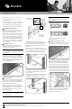
Orient the rails so that the notched end is toward the
rear of the LCD. Slip the rail’s first hole over the stud that
protrudes from the LCD assembly’s side. Fasten in place
using the supplied nut. The rear of the rail is secured to
the LCD assembly with a screw through the last hole of
the rail (see illustration below).
3
Installing the rack rails
Select a 1U location in the rack and install the appropiate
cage or clip nuts. Next, loosen the two rail-adjustment
screws on each of the outer slide rails and extend the rails
to their maximum length (see illustration).
Adjust the outer slide-rail brackets to fit the depth of the
rack cabinet, and then use four screws to attach the front
of the slide-rail brackets to the rack cabinet. Make sure
that the slide-rail brackets extend outside of the rack-
cabinet mounting flanges.
NOTE:
Do not install screws in the slide-rail bracket
middle holes. These holes are for the thumbscrews on
the front of the
LCD Tray.
Loosely attach the back of the slide-rail brackets to the
rack cabinet, using four screws. Ensure that the slide-rail
brackets extend outside of the rack-cabinet mounting
flanges. Tighten the two rail-adjustment screws on each of
the outer rails.
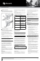
Next, loosen the front four slide-rail bracket screws and
insert the rail-alignment spacer between the finger brackets
and over the slide-rails. The rail-alignment spacer must
wrap around the rails to align and distance them correctly.
Brackets must fit snugly against the ends of the spacer
to establish proper gap. Tighten the front four screws and
remove the spacer.
Now, extend the inner part of the outer rails and slide the
ball-bearing assemblies forward to the front of the outer
rails making sure it is engaged with the plastic guide.
CAUTION:
Failure to engage the ball-bearing assembly
with the plastic guide (as shown below) can cause
damage to your rail.
Carefully slide the LCD Tray into the ball-bearing
assemblies in the rails.
4
Sliding the 17” LCD Tray into the rack
Press the release latches, and then push the LCD Tray
completely into the rack. There will be resistance initially
as the ball-bearing assemblies align between the inner
and outer rails. Pull the LCD Tray out halfway, and then
push it back in to seat the LCD Tray in the rails. Do this a
few times until the LCD Tray moves smoothly in the rails.
Push the LCD Tray into the rack, and then tighten the four
rear slide-rail bracket screws. Remove the rail-adjustment
screw that is closest to the rear of the rack from the outer
slide-rail bracket and discard. Loosen the Velcro® straps
on the cable retractor to allow free and smooth movement
of the cable retractor arm. Align the cable-management
arm (CMA) to the outer slide-rail bracket, and use the
removed screw to attach the CMA.
QUICK INSTALLATION GUIDE 17” LCD Tray
Rail-adjustment
screws
Lengthen/Shorten to Fit
NOTE: Slide rails have
been removed for
illustration purposes
Latch
LCD Tray
Spacer
Front of Rack
To Contact Avocent Technical Support: Visit www.avocent.com 590-980-501A
Avocent and the Avocent logo are registered trademarks of Avocent Corporation or its affiliates in the U.S. and other countries. All other marks are the property of their respective owners. ©2009 Avocent Corporation.
Latch
Stud
Nut
Screw
Inner part of
outer rails
extended
Front of Rack
Remove
existing screw
CMA