ESP-2 Multi-Interface Serial Hub Installation Guide 590-298-001C June 2003
Contents Introduction . . . . . . . . . . . . . . . . . . . . . . . . . . . . . . . . . . . . . . . . . . . 1 What You Get . . . . . . . . . . . . . . . . . . . . . . . . . . . . . . . . . . . . . . 1 Hardware . . . . . . . . . . . . . . . . . . . . . . . . . . . . . . . . . . . . . . . . . . . . . 1 Interfaces . . . . . . . . . . . . . . . . . . . . . . . . . . . . . . . . . . . . . . . . . . 2 Pin Assignments . . . . . . . . . . . . . . . . . . . . . . . . . . . . . . . . . . . . . 3 Electrical . . . . .
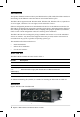
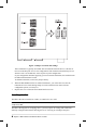
Introduction The Equinox Ethernet Serial Provider 2-port Multi-Interface (ESP-2 MI) Serial Hub contains an autosensing 10/100 Ethernet connection and two serial multi-interface ports. The ESP-2 MI is supported under Windows 2000, Windows XP, Windows NT 4.0, OpenServer 5.0.5a or higher, UnixWare 7.0.1a or higher, Linux and AIX 4.3 and 5.1. Software configurable parameters are downloaded to the device via the Ethernet connection.
The lower left area of the front panel contains two electrical connectors. You may use one of these, but not both. For more information, see Electrical. The LAN connector is used with a 10BaseT or 100BaseT LAN interface cable. A CAT 5 cable is required for 100BaseT operation. The two PORTS connectors are standard DB-9 DTE ports in RS-232 mode. The unit ships with RS-232 mode enabled for both ports. Table 2 describes the LEDs and buttons on the front panel.
When RS-422 signalling is set, the receiver and transmitter are always enabled. Pin Assignments Table 3 lists the pin assignments for the ports’ DB-9 connectors. This information is also provided on a label on the bottom of the unit.
• The unit also contains a 3-pin screw terminal block connector which provides connection for a 9 VDC to 30 VDC power source. The location of the positive, ground and negative pins are screened on the front panel. Surge protection is provided for each serial port up to 15,000 volts ESD. Technical Specifications Table 5 lists the ESP-2 MI technical specifications. Specification Operating Range Dimensions 4.75”W x 4.38D x 1.
6. 7. Figure 2. Jumper Locations and Settings This termination is typically used in RS-485 environments when the device is the first or last on a multi-drop line for a 2-wire configuration. This termination should always be set when the unit is set for RS-422, as this is point-to-point configuration. If your configuration includes supplying your own external termination, the termination on the ESP-2 MI should not be used. To disable termination, remove the jumper entirely.
Installing on a Table The unit ships ready to use in a tabletop environment. This includes four rubber feet on the bottom of the unit. At a later time, if you want to move the unit to a DIN rail or a wall installation, you can remove the rubber feet. Grasp the bottom of each foot and gently pull it down and out of the hole. Installing on a DIN Rail Equinox offers an Industrial Mounting Kit, part number 790226, containing hardware and instructions for mounting an ESP-2 MI on a DIN rail.
The INIT button on the front panel can be used to remove configured information from an ESP unit. The ESP stores nonvolatile data such as SNMP community name, system contact and IP address in the EEPROM. This information can be erased by pressing the INIT button. NOTE: Pressing the INIT button will interrupt ESP operation and cause reinitialization to occur. When the INIT button is first pressed, the ONLINE LED will begin to blink to confirm that you have pressed the INIT button.
1. 2. 3. Navigate to Settings - Control Panel - Add/Remove New Hardware. From the Add/Remove Hardware Wizard, select Add/troubleshoot a device. Windows 2000 will search for new Plug and Play hardware on your computer. ESP devices are network-attached and are not located by the Add New Hardware Wizard. A list of devices that can be installed will be displayed. Select Add a new device. 4. From the Find New Hardware page, select No, I want to select the hardware from a list. 5.
• Replace an ESP unit on a local or remote subnet See the online help in the ESP Installation Wizard for more information. OpenServer The following sections contain procedures for installing the ESP driver on an Open Server release 5.0.5a or higher system. Installing Directly from CD-ROM 1.
Creating OpenServer ESP Installation Diskettes on Windows 1. 2. 3. 4. Load the Equinox SuperSerial Software CD into your CD-ROM drive. • If you have autoplay enabled, the Equinox SuperSerial Software Installation screen will appear. • If you do not have autoplay enabled, set your default drive to D: and run the command D:\SETUP, where D: is your CD-ROM drive letter. Click UNIX on the Main Window. Select the UNIX operating system for which you need drivers.
3. 4. Select the UNIX operating system for which you need drivers. Follow the on-screen instructions for creating an installation diskette. Once the UnixWare installation diskette is created, refer to the following file for detailed installation instructions: /drivers/esp/unixware/readme.txt Linux The following sections contain procedures for installing the ESP driver on a Linux system. Creating Linux ESP Installation Diskettes on Linux 1.
AIX The following sections contain procedures for installing the ESP driver on an AIX release 4.3 or 5.1 system. Installing Directly from CD-ROM (AIX 5.1 only) This procedure is valid only on AIX release 5.1 systems. 1. Mount the CD-ROM volume using the following command: mount -v cdrfs -o ro /dev/cd0/mnt 2. Change to the RPMS directory using the following command: cd /mnt/RPMS/AIX51 3. Install the RPM using the following command: rpm -ivh ./espx-3.06.aix.5.1.ppc.rpm 4.
Creating AIX ESP Installation Diskettes on Windows 1. 2. 3. 4. Load the Equinox SuperSerial Software CD. • If you have autoplay enabled, the Equinox SuperSerial Software Installation screen will appear. • If you do not have autoplay enabled, set your default drive to D: and run the command D:\SETUP, where D: is your CD-ROM drive letter. Click UNIX on the Main Window. Select the UNIX operating system for which you need drivers. Follow the on-screen instructions for creating an installation diskette.
Displaying or Changing Network Configuration Values The Network Configuration window displays the ESP-2 MI unit’s IP address, subnet mask and gateway address. You must configure a nondefault IP address for the ESP-2 MI before the unit becomes operational. To display or change network configuration values: 1. 2. 3. Select Network Configuration from the Main Menu. Enter a valid value in the IP Address, Subnet Mask and Gateway Address fields. The addresses must be entered in standard IP dot notation.
• • • Amount of EEPROM configuration memory in kilobytes Unit’s MAC address Unit’s serial number This information cannot be modified. To display hardware information, select Hardware Information from the Main Menu. Displaying or Updating FLASH Memory The Flash Update window displays information about the current images loaded in FLASH memory. You may update the embedded application image or bootstrap image in FLASH memory.
• • • Allow administrative functions via SNMP - When enabled, the SNMP interface is used for monitoring and some configuration of the ESP-2 MI. When disabled, tools such as EquiView Plus and espdiag will not work. This feature is enabled by default. Allow web based interface - When enabled, the interface being used is available. When disabled, this interface is not available. This feature is enabled by default.
• Frame/Parity/Overrrun - Number of framing errors, parity errors and overruns since the unit was last rebooted. This window refreshes every five seconds. To display port statistics, select Port Statistics from the Main Menu. Displaying Connected Servers Information The Connected Servers window displays the following information about the servers that are connected to the ESP-2 MI.
To request a reinitialization: 1. 2. Click Initialize from the Main Menu. Click the Re-Initialize button. After the reinitialization and reboot, the web interface will try to reconnect to the unit, using the predefined IP address (192.1.1.1). If this fails, or if the web interface does not return within 30 seconds, direct your browser to the predefined IP address (192.1.1.1). You may also reinitialize the ESP-2 MI using the INIT button on the front panel.
Declaration of Conformity Manufacturer’s Name: Equinox Systems an Avocent Company Manufacturer’s Address: One Equinox Way Sunrise, Florida 33351-6709 USA declares, that the products Product Name: Model Name: Product Options: Year of Manufacture: Ethernet Serial Provider ESP-2 MI All 2003- conform to the following Product Specification: Safety: EMC: EN 60950 UL 60950 3rd Ed., CAN/CSA C22.2 No.
© 2003 Equinox Systems. All rights reserved. Reproduction without permission prohibited. Equinox and Avocent are registered trademarks or trademarks of Avocent Corporation. All other brands and product names are trademarks of their respective holders. Equinox makes no representations or warranties with respect to the contents hereof and specifically disclaims any implied warranties of merchantability or fitness for any particular purpose.
Equinox Systems One Equinox Way Sunrise, Florida 33351-6709 (954) 746-9000 Fax: (954) 746-9101 ftp.equinox.com www.equinox.com support@equinox.