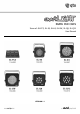
RGBW PAR CANS Item ref: SL-FC3, SL-36, SL-64, SL-SW, SL-Q8, SL-Q12 User Manual VERSION 1.
INTRODUCTION: LED SMARTLIGHT RGBW PAR CANS The QTX SmartLIGHT family of LED Par cans have been designed for a variety of applications, whether you’re a mobile DJ, a band/singer, a bar/nightclub, theater company or production company then this range of PAR cans will cover most requirements. Please read this manual carefully to ensure you get the best out of these products.
PACKAGE CONTENTS: Please check the contents to ensure that the product has been received in good condition. SmartLIGHT Box: SmartLIGHT Unit x 1pcs User’s Guide x 1pcs Power Cord x 2pcs (EU and UK) Mounting brackets x 2pcs Controller Box: SL-FC3 Controller x 1pcs 5m cable x 1pcs User’s Guide x 1pcs If you find any accessory is missing or the product has arrived with any problems, please contact your local dealer at once. Do not try to fix this item yourself or you will lose the warranty.
CAUTION! : TO PREVENT RISK OF ELECTRIC SHOCK AND ENSURE CORRECT USAGE For your safety, please kindly pay attention to all of the warnings listed below: Always plug in the power plug last and disconnect from the mains, when the device is not in use or before cleaning. Do not install and operate the device in rain or extreme heat, moisture or dusty environments. This device is for indoor use only and in a dry environment.
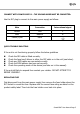
CONNECT WITH POWER SUPPLY – THE GROUND WIRE MUST BE CONNECTED: Use the IEC plug to connect to the main power supply as follows: Wire Connection International signal Brown Live L Blue Neutral N Yellow /Cyan Earth QUICK TROUBLE SHOOTING If the unit is not functioning properly follow the below guidelines Check Check Check Check Check the IEC cable is fitted correctly.
GENERAL MAINTENANCE To maintain optimum performance and minimise wear, fixtures should be cleaned frequently. Usage and environment are contributing factors in determining frequency. As a general rule, fixtures should be cleaned at least twice a month. Dust build-up reduces light output performance and can cause overheating. This can lead to reduced life and increased mechanical wear. Be sure to power off the fixture before conducting maintenance.
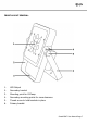
FRONT LAYOUT GENERAL: 1. LED Output 2. Secondary bracket 3. Mounting point for G-Clamp 4. Secondary mounting points for more clearance 5. Thumb screw to hold brackets in place 6.
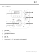
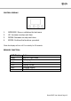
REAR LAYOUT SL-36: 1. LED Display 2. Sound sensitivity 3. IEC Power IN (Fuse F1A) 4. Microphone 5. DMX IN 6. DMX OUT 7.
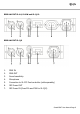
REAR LAYOUT SL-64, SL-SW and SL-Q12: REAR LAYOUT SL-Q8 1. DMX IN 2. DMX OUT 3. Sound sensitivity 4. Microphone 5. Connection to SL-FC3 Foot controller (sold separately) 6. IEC Power OUT 7.
CONTROL DISPLAY: 1. MODE\ESC: Menu or withdraw the last menu 2. UP: Increase one step each time 3. DOWN: Decrease one step each time 4. ENTER: Confirms the functions you select *Note the display will turn off if no activity for 20 seconds.
SECONDARY FUNCTION: A001-A512 Er_L AUT1 AUT2 AUT3 AUT4 SOU1 SOU2 SOU3 DMX-512 Address from 1 to 512 If there is a breakdown in the DMX connection Auto color switch Auto color switch , fade in & fade out effect (slow fade in – slow fade out) WRGB Color Scroll, fade in & fade out (slow fade in – quick fade out) Auto color mixing, Pastel scroll Sound Activated with colour changing mode Sound to light strobe all LEDs on.
DMX The fixture is equipped with 3-pin XLR connectors for DMX input and output. The SE connectors are wired in parallel. Only use a shielded twisted-pair cable designed for 3-pin XLRplugs and connectors in order to connect the controller with the fixture or one fixture with another. Building a serial DMX-chain: Caution: At the last fixture, the DMX-cable has to end with a terminator.
DMX OPERATIONS: DMX Channel 1 2 3 4 5 6 DMX Value 000-255 000-255 000-255 000-255 000-255 000-250 251-255 Function Red Colour 0-100% Dimming Green Colour 0-100% Dimming Blue Colour 0-100% Dimming White Colour 0-100% Dimming Master Dimming 0-100% Strobe Slow to Fast Sound Activated SmartLIGHT User Manual Page 13
SL-FC3 FOOT CONTROLLER: A combination of up to 32 SmartLIGHT fixtures can be operated by one SL-FC3 controller. SETUP: First connect the foot controller to the first fixture using the supplied cable as shown below. Connecting more than one fixture to the chain requires 3 pin DMX XLR Leads (available at most retailers).
Once all the fixtures are setup turn the power on and set the DMX address on each model to A001. For users who wish to use the sound to light 4 light chase sequences set the DMX to each of the following: Connecting in 4’s 1st PAR can = A001 2nd PAR can = A007 3rd PAR can = A013 4th PAR can = A019 If you are connecting more than four in a chain either start again or work backwards. Maybe try your own combination but note you may only connect up to a maximum of 32 PAR cans in any one sequence.
LED FOOT CONTROLLER OPERATION: SmartLIGHT User Manual Page 16
TECHNICAL SPECIFICATION: For more information visit www.avsl-qtx.
SmartLIGHT User Manual Page 18
SmartLIGHT User Manual Page 19
Errors and omissions excepted. Copyright© 2012. AVSL Group Ltd.