DM-X16 192 Channel DMX Controller USER MANUAL 154. 093UK Vers ion 1.
DMX 512 CONTROLLER SERIES Contents 1. Before you begin 1.1 What are included.................................. ....................................................... 1.2 Unpacking instructions............................................................................... 1.3 Safety instructions .................................................................................... 2. Installation 2.1 Features ...................................................................................................
DMX 512 CONTROLLER SERIES 1.1 What are included 1) 2) 3) 4) DMX-512 Controller DC 9-12V 500mA, 90V~240V Power Adapter Manual LED gooseneck lamp 1.2 Unpacking Instructions Immediately upon receiving a fixture, carefully unpack the carton, check the contents to ensure that all parts are present, and have been received in good condition. Notify the shipper immediately and retain packing material for inspection if any parts appear damaged from shipping or the carton itself shows signs of mishandling.
DMX 512 CONTROLLER SERIES 2. I NTRODUCTION 2.
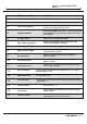
DMX 512 CONTROLLER SERIES Item Button or Fader Function 1 Scanner select buttons Fixture selection 2 Scanner indicator LEDS Indicates the fixtures currently selected 3 Scene select buttons Universal bump buttons representing scene location for storage and selection 4 Channel faders For adjusting DMX values, Ch 1~16 can be adjusted immediately after pressing the respective scanner select button 5 Program button Used to enter programming mode 6 Music/Bank Copy button Used to activate Musi
DMX 512 CONTROLLER SERIES 2.
DMX 512 CONTROLLER SERIES 2.5 Common Terms The following are common terms used in intelligent light programming. Blackout is a state by where all lighting fixtures light output are set to 0 or off, usually on a temporary basis. DMX-512 is an industry standard digital communication protocol used in entertainment lighting equipment. For more information read Sections DMX Primer and DMX Control Mode in the Appendix.
DMX 512 CONTROLLER SERIES 3.1.2 FIXTURE ADDRESSING The Controller is programmed to control 16 channels of DMX per fixture, therefore the fixtures you wish to control with the corresponding SCANNER buttons on the unit, must be spaced 16 channels apart.
DMX 512 CONTROLLER SERIES 3) Move one fader of 1-16 channel to select the pan channel. 4) Press the TAPSYNC DISPLAY button to select pan / tilt 5) Move one fader of 1-16 channel to select the tilt channel. 6) press and hold PROGRAM & TAPSYNC DISPLY Notes : All pan/tilt can be reassigned to output on a different DMX channel. buttons to exit and save setting. All LEDs will blink. 3.1.4 RESETTING THE SYSTEM Warning: this will reset the controller to its factory defaults.
DMX 512 CONTROLLER SERIES 3.2 Operation 3.2.1 MANUAL MODE The manual mode allows direct control of all scanners. You are able to move them and change attributes by using the channel faders. Action : 1) Press the AUTO DEL button repeatedly until the MANUAL LED is lit. 2) Select a SCANNER button. Notes : All changes made while in Manual Mode are temporary and will not be recorded. 3) Move faders to change fixture attributes.
DMX 512 CONTROLLER SERIES 3.3.3 RUNNING A PROGRAM Action : 1) Use BANK UP/DOWN buttons to change Program banks if necessary. 2) Press the AUTO DEL button repeatedly until the AUTO LED turns on. Notes : Deselect Blackout if LED is lit. 3) Adjust the PROGRAM speed via the SPEED fader and the loop rate via the FADE TIME fader. 4) Alternatively you can tap the TAPSYNC DISPLAY button twice. The time between two taps sets the time between SCENES (up to 10 minutes). Also called a Tap-Sync. 3.3.
DMX 512 CONTROLLER SERIES 3.4 Chase Programming A chase is created by using previously created scenes. Scenes become steps in a chase and can be arranged in any order you choose. It is highly recommended that prior to programming chases for the first time; you delete all chases from memory. See Delete All Chases for instructions. 3.4.1 CREATE A CHASE A Chase can contain 240 scenes as steps. The term steps and scenes are used interchangeably. Action : 1) Press the PROGRAM button until the LED blinks.
DMX 512 CONTROLLER SERIES 3.4.5 EDIT CHASE (COPY SCENE INTO CHASE) Action : 1) Press and hold the PROGRAM button to enter Notes : programming mode. 2) Press the desired CHASE button. 3) Select the BANK that contains the scene to be copied using the BANK UP/DOWN buttons. 4) Press the SCENE button that corresponds to the scene to be copied. 5) Press MIDI/ADD button to copy the scene. All LEDs will blink. 3.4.
DMX 512 CONTROLLER SERIES 3.4.9 DELETE ALL CHASE PROGRAMS CAUTION! This procedure will result in irrevocable loss of chase step memory. The individual scenes and program banks will be preserved. Action : 1) Turn OFF controller. 2) Press and hold the BANK DOWN button and the Notes : AUTO DEL button while turning ON the controller. 3) All LEDs will blink. 3.5 Scene Programming (Steps) 3.5.1 INSERT A SCENE Action : Notes : 1) Press and hold the PROGRAM button to enter programming mode.
DMX 512 CONTROLLER SERIES 3.5.3 DELETE A SCENE Action : 1) Press and hold the PROGRAM button to enter programming mode. 2) Select the BANK that contains the scene to be deleted by using the BANK UP/DOWN buttons. 3) Press and hold the AUTO DEL button. 4) Press the SCENE button that corresponds to the scene you want to delete. All LEDs will blink. Notes : When deleting a scene the physical location is not removed, however, all 192 DMX channels available to the scene will be set to value 0. 3.5.
DMX 512 CONTROLLER SERIES 3.6.3 BLACKOUT The Blackout button brings all lighting output to 0 or off. 3.7 Midi Operation The controller will only respond to MIDI commands on the MIDI channel which it is set to full stop. All MIDI control is performed using Note on commands. All other MIDI instructions are ignored. To stop a chase, send the blackout on note. Action : Notes : 1)Press and hold the MIDI/ADD button for about 3 seconds.
DMX 512 CONTROLLER SERIES 4 APPENDIX 4.1 DMX Primer There are 512 channels in a DMX-512 connection. Channels may be assigned in any manner. A fixture capable of receiving DMX 512 will require one or a number of sequential channels. The user must assign a starting address on the fixture that indicates the first channel reserved in the controller. There are many different types of DMX controllable fixtures and they all may vary in the total number of channels required.
DMX 512 CONTROLLER SERIES 4.
DMX 512 CONTROLLER SERIES 4.4 Technical Specifications 3m m 73m m 18 520 mm Dimensions.................................................................................................. 520 X183 X73 mm Weight........................................................................................................................... 3.0 Kg Operating Range.....................................................................................DC 9V-12V 500mA min Maximum ambient temperature..................