CL1200 MIXING CONSOLE Item ref: 170.
Caution: Please read this manual carefully before operating Damage caused by misuse is not covered by the warranty Introduction Thank you for choosing the CL1200 mixing console as part of your professional sound system. This product has been developed to provide a full arsenal of facilities and features to fulfill a comprehensive range of audio requirements with high quality, reliable results. Please read and keep this manual to achieve the best results from your purchase and avoid damage through misuse.
Console layout The CL1200 has comprehensive input and output sections which can be split further into various stages of processing and routing. All preamps have studio grade, low noise architecture for the cleanest possible path throughout the signal chain. The input stages are repeated across each channel of the console, which simplifies operation and enables quick and easy location of various controls.
Mic/Line Input Section Channel inputs and inserts are provided as XLR and/or 6.3mm jack sockets. The connections for these inputs are assigned as follows. 1. MIC input Balanced Unbalanced 2. LINE input Balanced Unbalanced 3. Connect balanced microphone to this XLRF input. An unbalanced microphone can be connected provided that +48V phantom power not used. Wired as follows.
Mic/Line EQ Section 7. HIGH This control can boost or cut the high frequencies (centre 12kHz) by ±15dB (12 o’clock position is zero) 8. FREQ This control sweeps the frequency band affected by the MID Control from 100Hz through to 8kHz 9. MID This control can boost or cut the mid frequencies set using the FREQ control by ±15dB (12 o’clock position is zero) 10. LOW This control can boost or cut the low frequencies (centre 80Hz) by ±15dB (12 o’clock position is zero) Stereo Line Input Section 11.
Stereo Line EQ Section 15. HIGH EQ This control can boost or cut the high frequencies (centre 12kHz) by ±15dB (12 o’clock position is zero) 16. HIGH-MID This control can boost or cut the high-mid frequencies (2.5kHz) by ±15dB (12 o’clock position is zero) 17. LOW-MID This control can boost or cut the low-mid frequencies (250Hz) ±15dB (12 o’clock position is zero) 18. LOW This control can boost or cut the low frequencies (centre 80Hz) by ±15dB (12 o’clock position is zero) Channel Routing 19.
Channel Faders 25. MUTE Pressing this switch in mutes the channel output (not Insert Send) A red LED indicates that the channel is muted. 26. PFL Pre-Fade Listen sends the channel signal direct to monitoring. This means that the channel signal is shown on the main VU LEDs. Also, the signal is routed directly to the headphones output. This allows the particular channel signal to be checked. If many PFLs or AFLs are selected, all are routed to monitoring.
35. 2 TRACK INPUT Left + Right RCA connection for auxiliary input of a playback device (e.g. CD or mp3) This can be routed to ST1 or main outputs (see 54 below) and is governed by the 2TK/PC rotary level control (52) 36. 2 TRACK OUT Left + Right RCA connection for main mix output to a recording device. This output is pre-fader (unaffected by main Left + Right faders) 37. FX / AUX SEND Unbalanced jack outputs from FX SEND or AUX SEND routes. The mix is governed by FX and AUX levels from each channel. 38.
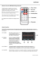
Remote Control for MPR Media Player/Recorder The MPR module is supplied with an infra-red handheld remote control to handle some of the onboard controls away from the console. Before use, it is necessary to pull out the tab at the base of the handset to engage the battery. This remote control is most effective in line of sight with the “IR” receiver on the MPR window. Key assignments are detailed on the diagram shown here.
Master Routing Section 50. FX SEND Overall level of signals routed to the FX Send buss, either for internal DSP or FX Send output (37). When using the internal DSP, it is important to observe the LED level meter on the DSP section (56) and if the signal is clipping (red LED lighting) to reduce the FX send level accordingly. 51. AUX SEND Overall level of signals routed to the AUX Send output (37). 52.
170.
Status Indicators The master section has 4 status LEDs, which indicate as follows. POWER PFL/AFL When lit, indicates that main power is on Pre-Fade or After-Fade Listen is active Main Output Level Meters The main output level meters comprise a pair of volume ladders with 15 LEDs in each. These normally display the main left and right output levels unless PFL or AFL is active.
Rear Panel 65. Combined IEC mains inlet, fuse holder and switch. Connect IEC to mains power using the supplied mains lead. Replace fuse only with type indicated. Illuminated rocker switch activates mains power to the unit.
170.
Troubleshooting No power LED on control panel Power LED is on but no other LEDs and no output Power light and VU LEDs lighting but no main output No output from stereo inputs No playback from USB or SD media No playback from PC interface No signal from PC interface to computer VU LEDs do not show MAIN output levels Graphic EQ has no effect on MAIN outputs Output is very loud or distorted Output is working but at very low level Feedback (loud squealing or howling from mics) Ensure mains outlet volta
Disposal: The “Crossed Wheelie Bin” symbol on the product means that the product is classed as Electrical or Electronic equipment and should not be disposed with other household or commercial waste at the end of its useful life. The goods must be disposed of according to your local council guidelines. Errors and omissions excepted. Copyright© 2014. AVSL Group Ltd. 170.