Item ref: 600.
Please read this manual thoroughly and ensure all contents are fully understood before using the apparatus. Warning To avoid possible electric shock or personal injury, and to avoid possible damage to the tester or to the equipment under test, adhere to these following rules: Before using the tester inspect the case. Do not use the tester if it is damaged or the case (or part of the case) is removed. Look for cracks or missing plastic.
Replace the battery as soon as the battery indicator appears. With a low battery, the meter may produce false readings that can lead to electric shock and personal injury. Remove the connection between the testing leads and the circuit being tested, and turn the meter power off before opening the meter case. The internal circuit of the meter shall not be altered at will to avoid damage of the meter and any accident.
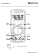
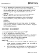
LCD Power Button HOLD Button Range switch A/mA terminal 10A terminal COM terminal VΩ terminal Multi-function adapter MTM01 User Manual
Multitester comparison table Model MTP01 DCV Y ACV Y DCA Y ACA Y Ω Y Y Y hFE Y Cap Y Technical Specifications Accuracies are guaranteed for 1 year, 23ºC ± 5ºC, less than 80% RH. DC Voltage RANGE 200mV 2V 20V 200V 600V RESOLUTION 100uV 1mV 10mV 100mV 1V ACCURACY ± (0.5% of rdg + 3D) ± (0.8% of rdg + 5D) ± (1.0% of rdg + 5D) Input Impedance: 10MΩ Overload Protection: 1000V DC or 750V AC rms Max. Input voltage: 1000V DC AC Voltage RANGE 200V 500V RESOLUTION 100mV 1V ACCURACY ± (2.
Audible Continuity RANGE DESCRIPTION Built-in buzzer sounds if resistance is less than 30±20Ω The approximate forward voltage drop will be displayed Overload Protection: 250V DC/AC rms Remark Open circuit voltage: about 2.8V Open circuit voltage: about 2.8V DC Current RANGE RESOLUTION 2mA 1uA 20mA 10uA 200mA 100uA 10A 10mA Overload Protection: mA: F0.5A/600V fuse 10A: F10A/600V fuse Voltage Drop: 200mV ACCURACY ± (1.8% of rdg + 2D) ± (2.0% of rdg + 2D) ± (2.
Resistance RANGE 200Ω 2KΩ 20kΩ 200kΩ 2MΩ 20MΩ 200MΩ RESOLUTION 0.1Ω 1Ω 10Ω 100Ω 1kΩ 10kΩ 100kΩ ACCURACY ± (1.0% of rdg + 10D) ± (1.0% of rdg + 4D) ± (1.0% of rdg + 10D) ± [5%*(rdg-10) + 10D) Open Circuit Voltage: about 3V Overload Protection: 250V DC/AC rms Capacitance RANGE 2nF 20nF 200nF 2uF 20uF RESOLUTION 1pF 10pF 100pF 1nF 10nF ACCURACY ± (4.0% of rdg + 5D) Overload Protection: F0.
OPERATING INSTRUCTIONS VOLTAGE MEASUREMENT 1. Connect red test lead to “VΩ” jack, black lead to “COM” jack. 2. Set RANGE switch to desired VOLTAGE position, if the voltage to be measured is not known beforehand, set switch to the highest range and reduce it until satisfactory reading is obtained. 3. Connect test leads to device or circuit being measured. 4. Turn on power of the device or circuit being measured voltage value will appear on Digital Display along with the voltage polarity.
2. Set the range switch to desired AC or DC position. If the current magnitude to be measured is not known beforehand, set the ranges switch to the highest range position and then reduce it range by range until satisfactory resolution is obtained. 3. Open the circuit to be measured, and connect test leads in SERIES with the load in with current is to measure. 4. Current reading will be displayed on LCD, for DC current measurement, the polarity of the red probe will also be indicated.
CAPACITY MEASUREMENT 1. Connect the BLACK test lead to the COM jack and the RED to the mA jack. 2. Set the Range switch at F position. (NOTE: The polarity of the RED lead is positive “+”) 3. Connect test leads across the capacitor under measure and be sure the polarity of connection is observed. Please Note: To avoid damage to the Meter, disconnect circuit power and discharge all high-voltage capacitors before measuring capacitance. The tested capacitor should be discharged before the testing procedure.
4. The meter will show the approximate forward voltage of the diode. If the connections are reversed, “1” will be shown on the display. TRANSISTOR hFE MEASUREMENT 1. 2. 3. 4. Set the range switch to hFE range. Connect the adapter to the “COM” jack and the “hFE” jack. Don’t reverse the connection. Identify whether the transistor is NPN or PNP type and locate Emitter, Base and Collector lead. Insert the leads of the transistor to be tested into the proper holes of the transistor test socket of the adaptor.
Replace the case bottom and reinstall the three screws. Never operate the meter unless the case bottom is fully closed. ACCESSORIES Instruction manual Set of test leads (red and black) 9V PP3 battery EN61010–1:2010 This product is classed as Electrical or Electronic equipment and should not be disposed with other household or commercial waste at the end of its useful life. The goods must be disposed of according to your local council guidelines. Errors and omissions excepted. Copyright© 2014.