
Technical data

PAGE 111
Interfaces
A3.2 Control Interface
A3.2.1 RS232 interface
The RS232 interface is used for the configuration and the operation of the
MAGIC TH2 Telephone Hybrid System via a PC. Because of future data trans-
mission applications this interface is designed as DCE (Data Communication
Equipment). To connect a PC you need a 1:1 connecting cable, in which Pin 2
and Pin 3 are not crossed. Additionally, Pin 5 GND must be connected. The
remaining Pins are not used.
A3.2.2 TTL/RELAY interface
Via this interface external control signals can be used.
NOTICE
Please notice that the function - input or output - of the Pins RXD and TXD is
determined by the interface type DCE or DTE. The Pin assignment is always
RXD for Pin 2 and TXD for Pin 3.
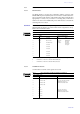
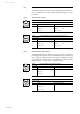
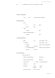
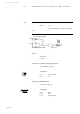
TAB. 8 PIN ASSIGNMENT: RS232 INTERFACE (RS232)
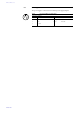
Socket: SUB-D, 9-pole
Pin Signal Electrical characteristics
1not usedType:DCE
a
Level: V.24
Data rate: 38400 Baud
Range: max. 15 m
Protocol: 1 Start bit
8 Data bits
1 Stop bit
a DCE = Data Communication Equipment: to connect a PC a 1:1 cable is required
2RXD
b
Receive Data
b ATTENTION: on this Pin the MAGIC TH2 transmits data
3TXD
c
Transmit Data
c ATTENTION: on this Pin the MAGIC TH2 receives data
4not used
5not used
6not used
7not used
8not used
9not used
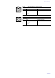
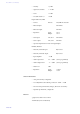
TAB. 9 PIN ASSIGNMENT: TTL/RELAY INTERFACE (TTL/RELAY)
Socket: SUB-D, 9-pole
Pin Signal Electrical characteristics
1 +5V/300mA Output
Capacity of the TTL outputs:
Maximum voltage: 5V
Maximum current: 10mA
Capacity of the relays:
Maximum voltage: 48V
Maximum current: 200mA
2 TTL 1 IN/OUT
3 TTL 2 IN/OUT
4 TTL 3 IN/OUT
5GND
6Relay 1a
7Relay 1b
8Relay 2a
9Relay 2b
5
1
9
6
5
1
9
6