Thank you for purchasing the IP camera tester. Please read the manual before using the IP camera tester and use properly. For using the IP camera tester safely, please first read the「Safety Information」carefully in the manual. The manual should be kept well in case of reference. Keep the S/N label for after-sale service within warranty period. Product without S/N label will be charged for repair service.
Content 1 .Safety information ............................................................................................................................... 1 2. IP Camera Tester Introduction ............................................................................................................. 2 2.1 General ...................................................................................................................................... 2 2.2 Packing list ........................................
(2)PING Test...................................................................................................................... 42 (3)Network test (Ethernet bandwidth test) ...................................................................... 43 (4)Port Flashing................................................................................................................. 46 (5)DHCP server .................................................................................................................
1 .Safety information ◆The tester is intended to use in compliance with the local rules of the electrical usage and avoid operating in areas which are inapplicable for the use of electrics such as hospital, gas station etc. ◆To prevent functional decline or failure, the product should not be sprinkled or damped. ◆The exposed part of the tester should not be touched by the dust and liquid.
2. IP Camera Tester Introduction 2.1 General The 4 inch IPS touch screen IP camera monitor is designed for maintenance and installation of IP cameras, analog cameras, TVI, CVI AHD cameras, as well as testing 4K H.264 /4K H.265 camera by mainstream, The 800x480 resolution enables it to display network HD cameras and analog cameras in high resolution. The unit supports many ONVIF PTZ and analog PTZ control. The combination of touch screen and key buttons make the IP camera tester very user- friendly.
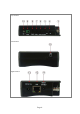
2.3 Function interface The charge indicator: it lights red while the battery is being charged. As the 1 charging is complete, the indicator turns off automatically The RS485 data transmission indicator: it lights red while the data is being 2 transmitted Page.3.
Top interface Left interface Right interface Page.4.
Bottom interface 3 Video image signal input(BNC interface)/ AHD,CVI and TVI input (BNC interface) 4 Power battery switch Return/Close: Return or cancel while setting parameters of the menu, close or decrease 5 the aperture 6 Confirm key (Long press it to capture screen interface) 7 Function switching key Press more than 2 seconds, turn on or off the device, short press to turn on or off the 8 menu display 9 RS485 Interface: RS485communication for the PTZ 10 LED lamp 11 DC12V3A power output, fo
3. Operation 3.1 Installing the Battery The tester has built-in lithium ion polymer rechargeable battery. The battery cable inside the battery cabin should be disconnected for safety during transportation! Prior to the use of the instrument, the battery cables inside the battery cabin should be well connected. Pressing the key continuously can power on or off the tester.
Note: If the IP camera requires PoE power, then connect the IP camera to the IP tester’s LAN port. The tester will supply PoE Power for the IP camera. Click on the icon labeled POE to turn the PoE Power off or on. 3.2.2 Analog camera connection (1) Connect the camera's video output to the IP tester’s VIDEO IN.
to connect CVI camera to the tester is also applied to CVI, TVI and AHD camera. (1) Connect the CVI camera's video output to the IP tester’s “Video IN” interface, the image will display on the tester. The tester only come with CVI input interface. There is no CVI output interface. (2) Connect the CVI camera or the speed dome RS485 controller cable to the tester RS485 interface. 3.
In Lite mode, click the finger icon in the lower right corner till yellow, long press the icon to move the function icon to other items. Do not click the finger icon and long press the application icon, then you can move the icon in the folder. Click SD card, install or remove SD card. Page.9.
3.3.2 Drop-down Menu Press and slide on the top right corner twice to open the shortcut menu. The shortcut menu includes POE power output, IP settings, HDMI IN, CVBS, TV OUT, LAN, settings etc. CVBS: Click icon “CVBS” to open CVBS application. LAN: Display network port or WIFI connection real-time upload and download speeds and other network parameters. Settings: Enter settings interface. IP: Enter IP Settings interface. Page.10.
POE power output: Turn on or off the tester “PoE power “app. 3.3.3 Screen capture Long press the key “enter”, then you can screen capture the interface and save it at any time. You can go to file management to view “file management –sdcard- Pictures—Screenshots”. 3.3.4 TesterPlay Mobile screen projection (Only for android version) The meter can create a WIFI hotspot, connect mobile phone to the tester’s WIFI hotspot, or connect the tester and mobile phone to the same Wi-fi network.
PC screen projection: Install VLC player in the PC, turn on the VLC player "Media - Open Network Streaming", and input the RTSP address on the top instrument two-dimensional code, click "play" to view the screen real-time projection. 3.3.5 Rapid video Page.12.
Press enter function, One key to detect all network cameras and auto play the images. Auto log in and display camera image. For detailed operation refer to ONVIF function After exit ONVIF app, Click Refresh to search ip address. Page.13.
3.3.6IP discovery Press IP discovery , tester will auto-scan the whole network segment IP, as well as auto-modify the tester’s IP to the same network segment with the scanned camera's IP. The meter will Auto-search for a connected a network segment, and will auto-add the IP of a different network segments. To detect unactivated Dahua and Hikvision cameras, click “OK”, go to Dahua and Hikvision Test Tool.
3.3.7 Rapid ONVIF test Rapid ONVIF can display 4K H.265/H.264 camera image by tester mainstream, one key to activate Hikvision camera Press enter ONVIF function, the meter will auto scan all ONVIF cameras on different network segments. It will list camera names and IP addresses on the Left side of the screen. Tester can auto log into camera and display camera image. Factory Settings use admin password to auto login, if you modified the password, then use the modified password to login.
When comes out “activate success” prompt, click login to display camera image. Pop-up settings menu when click the “ONVIF setting ” icon in the upper left corner Page.16.
Auto Login: After open this function, tester can auto login camera and display camera image (The login password is the same with last time, the first time using password is the default password "admin") Video transmission protocol: UTP and TCP protocol Open password cracker: Cracks password of cameras Show focusInfo:Focus Information. View manual: Open Manual Restore Defaults: Revert “Rapid ONVIF” to default settings Confirm: Save the modified parameters Click “MENU” icon to open camera setting .
ONVIF PTZ control: Tap the image in the direction you want the PTZ camera to move. Tap the left side of the image to move left, right to go right, up to go up and down to go down. Compatible IP PTZ cameras will rotate accordingly. PTZ rotation direction is displayed on top left corner of the image. IP camera video settings: Click “Video Set” to enter the IP camera’s encoder and resolution settings. Make the desired changes and click “OK “to save. Page.18.
Image setting: Click “Imaging Set” to adjust image brightness, saturation, contrast, sharpness and backlight compensation mode. Profiles: Click “profiles", can view video streaming current configuration files, as well as switch between Major stream and minor stream. Preview pictures: Quickly preview and zoom in or out pictures, automatically and manual refresh Identification: click “Identification” to view information of the camera. Page.19.
Time set: click “Time set”, Select " Manual set" to set up the time of camera Maintenance: For camera software reset or restore to factory settings. Page.20.
User Set: Modify camera user name, password etc parameters Network setting:Click “Network Set” to change the IP address. Some cameras cannot support change IP address, so there is no change after saving. If it is network video input to the tester, as the tester supports resolution up to 1080p, the input image will be very clear after it is enlarged. This is greatly helpful for the installers to ensure the IP camera’s video coverage and decide the IP camera’s install site.
Snapshot:Click bottom “snapshot” to screenshot the image and store it to SD card. if select manual storage, appears dialog box “Input Name”, user-defined the files name(by Chinese character, English letter ,or digit ) to save in SD card, if select “Auto- storage”, the tester auto stores the files after snapshot. Record:When you click the “Record” icon, video starts recording. A red recording icon will appear on the screen and begins to flash and a timer appears indicating the time elapsed for the video.
To rename or delete a photo, click and hold on the file until this screen appears: Lens simulation: To Simulate different lenses display fields, supported lens:“2.8/3.6/4/6/8/12/16/25mm", for choosing the suitable camera lens. Video files can play in the Video player on the main menu. PTZ Set preset position: To move the camera to the preset position, enter the preset number on the bottom right corner to complete position preset.
PTZ Speed set: Horizontal and Vertical Speed set RTSP: Get RTSP address of the current camera Doc: Auto generate test reports document of camera, click "Create document”. Click Preview to view the report document Page.24.
Enter the camera test information, click "Create Document" to complete the report. Click doc menu again, you can preview the report document. Page.25.
Icons description: the description of function icons on the bottom toolbar 3.3.8 IP camera test Display image from the 4K H.265 camera by mainstream Click icon to enter IP camera test Note: Currently, the IPC Test App only supports some brands’ specific IP cameras, these include specific models made by ACTI, AXIS, Dahua, Hikvision, Samsung, and many more. If the camera is not fully integrated, please use the ONVIF or RTSP apps. IPC test interface Local IP: This is the tester’s IP address.
Stream code: When test camera via RTSP, you can select mainstream or sub stream to test (if camera’s RTSP have not been start or without, it will tip “auto match fail, please witch to manually selecting” IP Camera's IP: Enter the IP camera’s IP address manually or click “Search” to auto-scan for the IP camera’s IP address. It is better to directly connect the IP camera to the tester so the search results will only display the camera’s IP address.
After all settings are completed, click “Enter” to view the live video If the IP address setting has an error or IP camera is not connected. The tester prompts “Network Error”. Click to quit from image display and return to IP camera test interface. Once you are able to view the video on the IPC Test app, you will see the “Video Menu” icon on the top right. This button will give you access to Snapshot, Record, Photo, Playback, PTZ, and Set.
Select relative function on the right side Toolbar to operate, functions including “Photos”, “Snapshot”, “Record”, “Playback”, “PTZ” , “Set” , Click , or press “Return” to quit. Click the screen twice quickly, to fully zoom in on the touch screen. (1) PTZ controller parameter setting Select and click icon “PTZ”, to enter PTZ setting: A. Protocol Use the up and down arrow keys to move the yellow cursor to the “protocol ”, set corresponding Protocols and support more than thirty PTZ protocols.
F. Tilt speed: Set the tilt speed of PTZ camera (0~63) G. Set preset position (Set PS) Click and select “Set PS”, set and save preset position number (1~128), H. Call the preset position (Go ps) Click and select “Set PS”, set and save preset position number (1~128), click “sure” to save, Call some special preset number, can call the dome camera menu Check and set the protocols, address, interface and baud, all must be consistent with the dome camera, then the IPC tester can test.
For analog video input, as the resolution is 720*480, it is normal that the zoom in image is not clear. But for network digital video input, as it supports resolution up to 960*540, the zoom in image is still very clear. This is very helpful for IP camera installation. (3) Snapshot Click the icon “Snapshot”, when the video in, to take a picture and save the current video frame in the SD card as JPEG file.
(5)Photo Click the icon “photo” to enter, click the selected thumbnail photo to display it on the screen. Double-tap the image to view it in full screen. Double-click again the photo to return. To rename or delete an image, click and hold on the file until this screen below appears. Page.32.
(6) Recorded video playback Click the “Playback” icon to view your recorded videos. Tap on the video file image you want to watch. To rename or delete a video, click and hold on the file until this screen appears: Video files also can play in the main menu “Video Player". 3.3.10 CVI camera test For HD CVI camera, CVI dome camera test and PTZ control, click icon to enter. With HD CVI signal input, the tester will display the image resolution on the top bar.
(1)PTZ control 1.1 Coaxial PTZ control Click the icon “PTZ” on the right toolbar to do the corresponding setting. “Port”: select coaxial control Enter PTZ address to perform parameters setting Page.34.
For operational instructions, please refer to “3.3.9 PTZ (1) Video monitor test”. The PTZ address in the tester must be consistent with the dome camera or decoder,in order for the IPC tester to detect the PTZ dome. After setting the parameter, the tester can control the PTZ and lens. To control PTZ by touch screen: Tap left, right, upward and downward on the touch screen to control the PTZ rotation direction, PTZ cameras will rotate accordingly.
Call preset position: Tap the preset position area, input preset position number. Tap “call position” to complete call preset position. 1.2 RS485 control Page.36.
For operational instructions, please refer to “3.3.9 PTZ (1) PTZ control parameters setting” (2)Coaxial camera menu setting Tap icon “UTC”, select “menu setting” to enter the dome camera menu Input calling dome camera menu address code, after finishing the parameter settings, you can press the key “Enter” or click the icon to call the dome camera menu. set the parameters with Page.37.
(3) Snapshot, record, photo viewer and video play back, please refer to “3.3.9 PTZ (1) Video monitor test”. Tap “close menu” to exit the camera menu. (4) Save setting Click icon “Set” on the right toolbar to enter storage setting. Support auto-storage and manual storage. When manual storage is selected, user can name and store the files. Page.38.
3.3.11 TVI camera test HD TVI camera, TVI dome camera test and PTZ control, Click icon to enter When HD TVI signal input, the tester will display the image resolution on the top bar. Double-tap on the screen to make the image display in full screen.
Tap icon “UTC”, then select “menu setting” to enter the dome camera menu Input calling dome camera menu address code, after the parameter settings are finished, you can press the key “Enter”or click the icon to call the dome camera menu For more operational instructions (such as PTZ control, coaxial camera menu setting, snapshot, recording, playback, etc.) please refer to “3.3.10 CVI camera test” 3.3.
screen to make the image display in full screen. The tester supports resolution as follows: 1280x720P 25FPS / 1280x720P 30FPS / 1920x1080P 25FPS / 1920x1080P 30FPS/2048x1536P 18FPS/2048x1536P 25FPS/2048x1536P 30FPS /2560x1440P 15 FPS/2560x1440P 25 FPS/ 2560x1440P 30 FPS/2592x1944P 12.
For more operational instructions please refer to “3.3.10 CVI camera test” 3.3.13 Network tool (1)IP address scan Connect the cable to the LAN port, click icon to enter, Set your IP address search range by changing the Start and End IP addresses. Click the “Start” button to scan for local IP addresses. You can also input an IP address in the Port Number Scan to scan for open ports. (2)PING Test Connect a network cable to the LAN port and click the icon to open the PING tool.
Application: PING testing is the most conventional network debugging tools. It is used to see if the connected IP camera or other network equipment’s Ethernet port are working normally and see if the IP address is correct. It’s normal that the first data packet will be lost when test start. (3)Network test (Ethernet bandwidth test) Network test (Ethernet bandwidth test) To use the Network tester, you will need two IP testers. One is used as a Server and the other as a Client.
b). Start send packet test: Using the other IP tester, type in the Server's IP address at the top right corner of the screen. This app is used to send packets for network speed testing. Click the “Start” button to send the packets and start testing. Network bandwidth testing can also be tested with a computer using compatible network bandwidth testing software. Install network bandwidth testing software on a computer, and use as a test Client or Server to perform the mutual testing with the tester.
Or use tester as a Server, computer as test Client(select Client, input tester’s IP address to test) When use tester as Server, shows results: Page.45.
(4)Port Flashing Connect a network cable to the meter’s “LAN” port, click the icon to open the Port Flashing app. Click “Start”. The IP tester will send an unique signal to make the connected LAN port of the switch flash.
(5)DHCP server Click on the DHCP icon to open the DHCP server app. Select the “Start” check box at the top and make any desired changes to the network settings. Click “Save” to start assigning dynamic IP addresses for IP cameras and other network devices. Click the “Refresh” button to check your Client list. (6)Trace route It is used to determine path of the IP packet access target.
(7)Link monitor Click the icon to open the Link Monitor app. This app is used to see if an IP address is occupied by other network devices. This will avoid new address conflicts. Click “Add” and enter the desired IP address. To test different network segments, click the “Settings” icon on the main menu and go to IP Settings and make the desired changes. Once the desired IP addresses are added to the Link Monitor list, click “Start”.
not be occupied, otherwise it will result in IP conflicts and stop the equipment from functioning properly. Link monitor can check if the new setting IP address is occupied. 3.3.14 Rapid IP Discovery Connect the cable to the tester’s LAN port. Press to enter Rapid IP Discovery app. Click “Start” to search all IP address of connected equipment in the whole network segment. Click “Stop” to stop work. 3.3.
2. Make sure to not put DC12V/3A in the DC12V/IN port in order to avoid damage to the port. 3. The IPC tester power output is close to 3A, if the IP camera’s power is over 3A, the tester will automatically enter protection mode. Disconnect all connections to the tester and then connect the power adaptor to the tester before using the tester. 4. Before turning on the PoE power output, please make sure the IP camera supports PoE power. Otherwise it may damage the IP camera. 5.
. Control keyboard The DVR or Control keyboard will send the code to the tester, if it can be read, the protocol will show on the upper right, like Pelco D, if not, like P:--While the tester receives the code, press the “Return” key to empty. Through the RS485 port, display the PTZ control code on the multifunctional keyboard or the DVR. Controller can check the status of the RS485 transmission through the code on the display. (The RS485 communication rate must be the same.
MPEG4, and MKV. The IP tester recorded files can play directly via the Media player. The Media player will automatically display the video files from the SD card. Click on the desired file to play. Click RETURN to exit. To rename or delete an existing file, hold down on the file name for a few seconds until the screen below appears. You can then rename or delete the file by pressing the desired option. 3.3.20 RTSP Player The RTSP Player app will allow you to view the RTSP video stream from an IP camera.
RTSP Add: This is where you can manually enter the IP camera’s RTSP URL or click on “Search” to search the network for cameras that use an RTSP stream. IPC Username: Enter the IP camera’s user name. IPC Password: Enter the IP camera’s password. Once you have entered all the necessary information, select Enter at the bottom left to view the RTSP stream. Note: in the event the IP tester does not auto detect the RTSP stream, refer to the specific camera manufacturer for the specific RTSP stream url.
2.Input password:Input new password, tap “ok” to activate 3. Confirm activation After activating the camera, the program default will modify the camera’s IP. Multiple active cameras in the local area Network, that are operating on the same IP address will improve efficiency. Play: Display image from the camera Page.54.
Modify network information: Change the camera IP address, subnet mask and gateway etc. Modify user information: Modify the camera's user name and password. Factory Reset:Camera factory reset 3.3.22 Dahua test tool Dahua test tool can be used for installation and debugging Dahua IP cameras, it can also display image, and modify IP, user name and password etc. Making Dahua camera testing more convenient and effecient. Support Batch activation Dahua camera and network segment modification.
Select the camera on the online detection menu, if the camera supports non-verification login, you can click “play” directly, and view the image. Pop up stream menu, select mainstream or second stream to test If the camera does not support non-verification login, please select “camera” on the online detection menu, and input correct user name and password, then click “log in”. After logging in, you can test it.
Modify user information: modify camera user name and password, which is either ONVIF, Dahua test tool, or IPC TEST user name and password, not web user name and password. Factory reset setting: camera will be soft reset, and the device’s user name, password and network set be saved. All ther setting information will be factory defaulted. 3.3.23 Update Copy the downloaded update file to SD card "update" directory, if no directory, please create one. Page.57.
Click the icon to open the Update menu. Select “Local Update” to update via the SD card or select “Online Update” to check for updates on the internet. If there are applications that need updating, the applications will be listed in the interface, click related applications, update to the latest version. Online update: Connect the Internet to update the apps. System update: Connect the Internet to update systems. 3.3.24 Office Quick office app (support excel, word, ppt format) doc. editable Page.58.
3.3.25 LED Flashlight It is convenient for the installation or maintenance in the evening or in the dark. Click icon to use. While in the flashlight app, click the red button to turn on the LED lamp. Press it again to turn it off. If you don’t press the red button to shut off the lamp and press the button to exit the app, the lamp will stay on. Click the Time Setting button to set a timer that will auto shut off the lamp after set time. 3.3.
the camera. If they are not in the same segment, press “RETURN” to exit. Open the “Settings” app from the main menu to change the IP tester’s network settings to match those of the IP camera. 3.3.27 Notepad: Notepad can be used to record the important testing results, click the key “Save” to save the contents. Notepad can auto record the storage, date, and time. . pls click to view the notepad, all saving contents that is displayed. Click each record bar to show the details.
3.3.28 System Setting Click icon to enter Language: Select your desired language: English, Chinese, Korean, Russian, Italian, Polish, Spanish, French or Japanese Typewriting: You can select typewriting or install other typewriting: Date/Time: Set the Date/time of the IP tester IP setting: Manually set the IP address, Subnet Mask, Default Gateway and DNS address or select “Dynamic allocation” to use DHCP. To test multiple network segments, click “Advanced” and then click Page.61.
“Add” to enter another IP address for the IP tester WLAN Net: Turn WiFi off or on by pressing the “Open the WiFi” button. Once WiFi is turned on, and click connected WiFi, it will scan for wireless networks in your area. Select and press “WIFI” several seconds, to set static IP address Wi-Fi hotspot: input “SSID” name and “password”, and then click “ok” to create Wi-Fi hotspot. Page.62.
Brightness: Set the desired brightness on the IP tester and adjust the sleep time settings. Volume: Set volume level SD Card: Displays SD Card Capacity. You can also format the SD card or unmount it before removing it. FTP server: Once the IP tester connects to a network, a computer can be used to read the SD card files via FTP Start the FTP server and then input the tester’s FTP address in the PC’s address bar.
Version information: Shows applications version information, holding down on any app icon for several seconds will uninstall the app. Screen display rotation: Click on “Screen Rotation” to flip the IP tester’s display 180 degrees. This function is very convenient for the user to connect the LAN cable on the bottom of the unit without having to flip the unit itself. PTZ address scan: Toggle the PTZ Address scan off or on before entering the “PTZ controller” app.
draw a new lock pattern. Restore the factory settings: If the tester is restored to factory settings, all your personal files and apps will be removed. 3.3.29 File explorer Click “File” on the top bar tool, then select internal or external storage. Click on the upper right corner Icon “...”. will bring up the pop-up menu, you can select other operations or exit Browse Browse includes Music, Videos, Pictures, Documents, zip file etc. It is a convenient viewer and manager. Page.65.
FTP server You can choose internal or external SD card. For other operational details, Please refer to FTP settings 3.3.30 Theme Click Theme icon to enter the themes setting. Desktop style : you can select Lite mode or normal mode. Theme: Holding down on any of the color icons for several seconds, the selected color icon will be moved into the rectangle area, if you hold down on the selected color several seconds, and it will be auto deleted.
Color To set background color, you can select colors from Color Phase or input the color’s RGB to set. Once you are done with the color setting, click “set” to set it as either desktop or application background. Set as desktop background: Setting color as desktop background Set as application background: Set color as application background Set at the same time: Setting color as desktop background and application background. Cancel: Cancel current setting.
Sliding effect: Tester’s sliding effects includes stereo, folding, Left and right folding, rotate, Ombre effect etc., selecting one of effect to view slide effect in the square area, and click “set” to save. 3. 4 Audio test You can test the audio input from audio pickup devices by connecting the audio pickup device to the IP tester with the supplied audio cable. Page.68.
3.5 PoE power output The IP tester supports PoE (Power over Ethernet) output to an IP camera via the LAN port. Data transmission and 48VDC use the network cable’s 1, 2, 3, and 6 pins to deliver power. If the IP camera supports PoE, you can directly connect to the camera without the use of an external power supply. Notice a. Please make sure the cable connected to the tester’s Lan port is straight-line cable and has no short circuit, otherwise it could potentially damage the tester. b.
Application Power output function is mainly used in the camera field demonstration and testing, meanwhile, for some camera installation sites, if there is no power outlet for the adapter to power the camera, the tester can offer temporary power for it. We do not suggest using the tester as a power supply for a prolong period of time. Notice: a. Do not supply any power into the “DC12/3A OUTPUT” port of the tester b. Man-made damage is not within company warranty c.
4. Specifications 4.1 General Specifications Model Display Network port WIFI H.265 Main stream test IP discovery IP Camera Tester New 4inch IPS touch screen cctv tester 800x480 resolution 10/100/1000M auto adjust, RJ45 Built in WIFI,speeds150M,display wireless camera image New hardware decoding, 4K H.265/H.
1 channel AHD input(BNC interface),resolution support 720p 25,30fps / AHD video signal test 1080p 25,30fps/2048x1536p 18,25,30fps , 2560x1440p 15,25,30fps/ 2592x1944p 12.5,20fps UTC control and call OSD menu Analog video test 1 channel BNC Input , NTSC/PAL (Auto adapt) Snapshot, Video Capture current images and record live video as JPG file.
OSD menu, select your desired language: English, Chinese, Korean, Operation setting Auto off Russian, Italian, French, Polish, Spanish, Japanese etc 1-30 (mins) General Working Temperature -10℃---+50℃ Working Humidity 30%-90% Dimension/Weight 126mm x 83mm x 33mm / 0.32kg The data above is only for reference and any change of them will not be informed in advance. For more detailed technical inquiries, please feel free to call the Technical Department of our company. Page.73.