
User Manual

Alarm Management
NVR User Manual
76
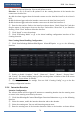
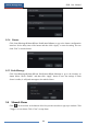
③ Select the line and direction. You can add 4 lines at most.
Direction: A<->B, A->B and A<-B optional. It is the crossing direction of the intruder who
crosses over the alert line.
A<->B: the alarm triggers when the intruder crosses over the alert line from B to A or from A
to B.
A->B: the alarm triggers when the intruder crosses over the alert line from A to B.
A<-B: the alarm triggers when the intruder crosses over the alert line from B to A.
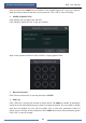
④ Draw the alert surface. Refer to the interface as shown above. Check “Draw line” and then
drag the mouse in the image to draw an alert line. Uncheck the “Draw line” if you finish the
drawing. Click “Clear” button to delete the alert line.
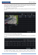
⑤ Click “Apply” to save the settings.
⑥ Click “Processing Mode” to go to the alarm handling configuration interface of line
crossing detection.
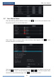
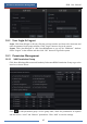
Line Crossing Alarm Handling Configuration:
① Click StartSettingsAlarmIntelligence AlarmTripwire to go to the following
interface.
② Enable or disable “Snapshot”, “Push”, “Alarm-out”, “Preset”, “Buzzer”, “Pop-up Video”
and “E-mail”. The alarm handling setting of line crossing alarm is similar to that of the sensor
alarm (see 9.1 Sensor Alarm for details).
③ Click “Apply” to save the settings. You can click “Crossing Config” to go to the line
crossing configuration interface.
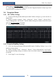
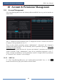
9.3.4 Intrusion Detection
Intrusion Configuration:
The relevant alarms will be triggered if someone or something intrudes into the warning areas
or moves in the warning areas drew by the users.
① Click StartSettingsCameraIntelligent DetectionIntrusion to go to the following
interface.
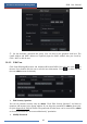
② Select the camera, enable the intrusion detection and set the duration.
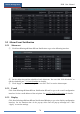
③ Select the warning area. You can add 4 warning areas at most.
④ Draw the warning area of the intrusion detection. Refer to the interface as shown below.