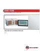
EMO-3000 MULTI CHANNEL FLOW COMPUTER Operation & Installation Manual Rev.
EMO‐3000 Operation and Programming Manual Table of Contents Safety Definitions and Information ............................................................................................................... 5 Unpacking ..................................................................................................................................................... 5 Quick Start Guide .........................................................................................................................
EMO‐3000 Operation and Programming Manual Linearizer Operation ................................................................................................................................... 17 Main Menu .................................................................................................................................................. 18 General Operation ......................................................................................................................................
EMO‐3000 Operation and Programming Manual 1 = ACTION RATIO ............................................................................................................................... 31 Quick Programming ................................................................................................................................ 32 2 – QUICK PROGRAM .......................................................................................................................... 32 Fluid Variables ............
EMO‐3000 Operation and Programming Manual mA Pointer .......................................................................................................................................... 45 mA Shifter ........................................................................................................................................... 45 Programmable Variables .........................................................................................................................
EMO‐3000 Operation and Programming Manual Safety Definitions and Information Do not attempt to install or use your AW Gear Meters product until you have read the safety instructions in this section. Save this manual and keep it in an easily accessible place. Warning! Warning means that failure to follow this safety statement may result in extensive product damage, serious personal injury, or death.
EMO‐3000 Operation and Programming Manual Quick Start Guide Caution As with any precision‐engineered device, always operate the EMO‐3000 in accordance with the manufacturer’s instructions. Connect to Flow Transmitter You will connect three wires from a sensor to the back of the EMO‐3000 (see samples in Appendixes J, K, L, M, and N). Insert the electrical power (red), signal (white), and ground (black) wires to the appropriate terminals. Secure with a screwdriver. Notice Color of wires may vary.
EMO‐3000 Operation and Programming Manual Principle of Operation (Example: Paint Application) A PLC transmits flow instructions to the EMO‐3000. The EMO‐3000 then uses an I/P converter and pneumatic pressure to control the fluid regulator. The meter measures the flow to the paint nozzle. The EMO‐3000 compares this value to the set‐value and makes any adjustments required. The device’s internal memory retains flow values from earlier cycles and continuously modifies them as new conditions occur.
EMO‐3000 Operation and Programming Manual 4‐20 mA or 0‐5 V output Power supply: 110/220 Volts AC, 50/60 Hz DM‐3000 Hardware In most cases, install the DM‐3000 using the 9‐Pin D‐Sub power/communication cable shipped with the unit. Standard cable length is 15 feet; maximum length is 50 feet. Longer lengths, though not recommended, can be accommodated. The environment through which you lay the cable determines interference level.
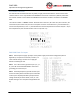
EMO‐3000 Operation and Programming Manual 15‐Position Connector On channel cards manufactured after July 1993, an eight‐position DIP switch is used to set the cards’ channel number. This is only available if the EPROM has channel FF marked on it (default). Otherwise the channel number is hard‐coded in the EPROM and the channel number is marked on the EPROM label. The channel number is a BINARY number.
EMO‐3000 Operation and Programming Manual PIN 4 Primary frequency input A. The input is used for the primary flow transmitter for Monitor, PID*, and Ratio modes. The input has an opto‐coupler isolation circuit and a 4‐position frequency divider chip (refer to Appendix H and Q). PIN 5 4 ‐ 20 mAmp (+) input. This normally serves as the set point input for the PID mode. The isolation to ground is 400 Kohms. PIN 6 4 ‐ 20 mAmp (‐) input current loop return for pin 5. PIN 7 4 ‐ 20 mAmp output.
EMO‐3000 Operation and Programming Manual Monitor Mode (operating mode = 01) Monitor Mode is used for applications where it is important only to monitor flow rates and totals. This mode also provides analog and limit outputs. The programmable limit values turn a relay contact either ON or OFF. The 4‐20 mA or 0‐5 volt analog outputs can be scaled to the flow rate or the total, which can be recorded in strip chart form, as a digital recording, or sent to a PLC via the serial communication link.
EMO‐3000 Operation and Programming Manual Integral This variable is used in slow reacting, closed loop systems where a high proportional factor causes the unit to go in to oscillation. In most cases, it is best to make a design change to improve the system and hysteresis† before employing this variable. Derivative The derivative part of the PID formula works against the proportional part if the general direction is towards the selected set‐value. Often used to stabilize the instability of high gain factors.
EMO‐3000 Operation and Programming Manual ma‐Scaler The milliamp scaler scales the 0 ‐ 20 mAmp input signal on Pin 5 and 6 to the flow rate in engineering units/mA. For example: 20mA = 1000 cc/min. Then, 1000 B = mA‐Scaler where B = 20mA ‐ mA offset value. With a mA Offset Value of 4mA, then mA‐Scaler = 62.5 cc/min or 1mA = 62.5 cc/min. This signal serves as a flow rate setpoint in the PID mode after scaling.
EMO‐3000 Operation and Programming Manual Input‐Ouput Pin Control You can set pins 11‐14 as inputs or outputs – it depends on the operating mode you select. In monitor mode, all of the pins are limit outputs. In PID mode, pins 11, 12, and 13 are inputs, while pin 14 is an output. By setting these Inputs and Outputs to suit the needs of the operating mode, as shown below, you can take advantage of the LIMIT programming and PID the special functions for more efficient operations.
EMO‐3000 Operation and Programming Manual Limit Operations You can set up the EMO‐3000 for 4 Limit Outputs by changing the factory‐set opto‐coupler arrangement from the PID settings of 3 inputs and 1 output to the Monitor Mode settings of 4 outputs. You can program any opto‐coupler set for an Output to react to the following functions according to the LIMIT RULE programmed. See page 27.
EMO‐3000 Operation and Programming Manual Ratio 1 +/‐ % = XXXXX. Ratio 2 +/‐ % = XXXXX. Ratio 3 +/‐ % = XXXXX. Ratio 4 +/‐ % = XXXXX. Notice The Flow Margin operates as +/‐ the programmed amount before tripping the Limit. For instance, if Flow Limit 1 is programmed to 100 cc/m and the Flow Margin 1 is programmed to 10cc/m, the Limit 1 turns on anytime the Flow Rate goes below 90 cc/m or above 110 cc/m.
EMO‐3000 Operation and Programming Manual Linearizer Operation The EMO‐3000 features a fully programmable 10‐point linearizer. The linearizer corrects for errors over the flow transmitter’s indicating range using the calibration data. The linearizer can only be used if there is an accurate calibration for that particular flow meter in the range required. The linearizer can be used in any operating mode: Monitor, PID, or Ratio.
EMO‐3000 Operation and Programming Manual Main Menu The Main Menu appears below. There are six selections possible. **** DM‐3000 MAIN MENU V2.0.97 F1=ACTION DSP F2 = SINGLE CHANNEL F3=RATIO DSP F4 = PROGRAMMING F5=SEARCH CHA F6 = UTILITY 1=ACTION RATIO 2 = QUICK PROGRAM 3=FLUID VARIABLES 4=............ SELECT ONE OF THE ABOVE ALTERNATIVES In any of the Action or Programming screens, ESCAPE returns you to the Main Menu. Choices are explained on the following pages. F1 = ACTION DISPLAY ........
EMO‐3000 Operation and Programming Manual F1 = ACTION DSP (Rate) CNR 01 02 03 04 05 06 F1=ESC RATE XXXXX.X XXXX.XX XXX.XXX XXXX.XX XXXXX.X XXXXXXX F2=RATE CNR 07 08 09 10 11 12 F3=TOTAL RATE XXXXX.X XXXX.XX XXX.XXX XXXX.XX XXXXX.X XXXXXXX F4=GRAND TOTAL CNR 07 08 09 10 11 12 F6=RESET ALL TOTAL XXXXX. XXXXX. XXXXX. XXXXX. XXXXX. XXXXX. CNR 07 08 09 10 11 12 F6=RESET ALL GRAND TOTAL XXXXX. XXXXX. XXXXX. XXXXX. XXXXX. XXXXX. ACTION DSP (Total) CNR 01 02 03 04 05 06 F1=ESC TOTAL XXXXX. XXXXX. XXXXX.
EMO‐3000 Operation and Programming Manual SINGLE CHANNEL DISPLAY 1 MONITOR MODE DSP 01 RATE = XXXX.ccm TOTAL = XXXX.cc GRAND = LIMIT 1 ‐ ‐>OFF LIMIT 2 ‐ ‐>OFF LIMIT 3 ‐ ‐>OFF LIMIT 4 ‐ ‐>OFF F1=ESC F2=CHNL UP F3=CHNL DN CHANNEL = XX XXXX.cc F5 = D+ F2 pages UP through the channels. F3 pages DOWN through the channels. F5 calls up PID displays 2 and 3. Below is the second of the two single channel display screens. Select F5 = D+ in the first screen to enter this screen.
EMO‐3000 Operation and Programming Manual SINGLE CHANNEL DISPLAY 1 ‐ PID P I D MODE RATE = XXXX.X ccm SET = XXX.XX ccm TRANSPARENT ‐ ‐ > OFF HOLD ANALOG ‐ ‐ > OFF HOLD TOTAL ‐ ‐ > OFF SET REACHED ‐ ‐ > OFF F1=ESC F2 = UP DSP 01 CHANNEL = XX FLUID NBR = 00 mA OUTPUT = 00.00 F3 = DN F5 = D+ F2 pages UP through the channels. F3 pages DOWN through the channels. Notice The channel selection for programming is performed in this screen. F5 calls up the second Single Channel screen.
EMO‐3000 Operation and Programming Manual SINGLE CHANNEL DISPLAY 3 ‐ PID VARIABLES P I D MODE DSP 03 FLU = 00 GAIN = XXXX. mA SCALER = XXXXX. TOLERANCE = XXXX. KFR FACTR = XXXXX. I‐KICK = XXXX. I‐PART = XXXXX. MA OFFSET = XX.XX D‐PART = XXXXX. SAMPLE AM = XXXXX. CUTOFF = XXXXX. DELAY XXX.XX DELTA STP = XXXXX. F1=ESC F2 = FLU UP F3 = FLU DN F4 = RES CHANNEL = XX F5 = D+ F2 pages UP through the Fluid Numbers. F3 pages DOWN through the Fluid Numbers.
EMO‐3000 Operation and Programming Manual F3 = RATIO DISPLAY Use F3 on the Main Menu to select the Ratio Display Screen. This operation screen shows both the rates from frequency inputs A and B, and the Ratio A/B. RATIO DISPLAY FOR CHANNEL XX RATE A= RATE B= RATIO A/B= SET RATIO= F1=ESC XXX.X ccm XXX.X ccm XXX.XX XX.XX F2=CHNL UP F3=CHNL DN F2 pages UP through the channels. F3 pages DOWN through the channels.
EMO‐3000 Operation and Programming Manual Notice You can view and reprogram all variables via the F2 function shown above (General A). The other F keys shown above provide shortcuts to specific sections of the variable table. Page 46 shows a full list of variables. The choices are explained on these pages.
EMO‐3000 Operation and Programming Manual Use F2 to page through the General A menu to access all variables. Use the following procedure to change a value: F2 Use page up to move the variable up to a position next to the printer. F4 Allows programming. 4146 You only need to enter the pass code once for multiple changes. Enter new digits from left to right. Further prompts appear at the foot of the display. F3 = PID VARIABLES ‐‐‐> F1=ESC PID PID PID PID PID PID PID F2=PGUP VARIABLES PROPORT.
EMO‐3000 Operation and Programming Manual ENTER PASS CODE = XXXX The code is 4146. Key in the correct value and Enter with F6. F5 = ANALOG VARIABLES * * * ANALOG VARIABLES * * * CH = XXX ‐‐‐‐> mAs OFFSET = XXX.XX mAs GAIN = XXXXX. mAs SHIFTER = XXXXX. mAs POINTER = XXXXX. Volts OFFSET = XX.XXX Volts GAIN = XXXXX. F1 = ESC F2 = PGUP F3 = PGDN F4 = PRGM Notice Use F2 = PGUP to access the four variables in the ANALOG VARIABLES screen. These variables are: Volts SHIFTER = XXXXX. Volts POINTER = XXXXX.
EMO‐3000 Operation and Programming Manual Notice Use F2 = PGUP in the LIMIT VARIABLES screen to access the following variables: FLOW FLOW FLOW FLOW FLOW FLOW LIMIT 2 = MARGIN 2 = LIMIT 3 = MARGIN 3 = LIMIT 4 = MARGIN 4 = XXXX.X XXXX.X XXXX.X XXXX.X XXXX.X XXXX.X When the desired variable is moves to the arrow, select F4 = PROGRAM. The DM‐3000 then asks for the pass code. ENTER PASS CODE = XXXX The code is 4146. Key in the correct variable value and Enter with F6.
EMO‐3000 Operation and Programming Manual When the desired variable is moves to the arrow, select F4 = PROGRAM. The DM‐3000 then asks for the pass code. ENTER PASS CODE = XXXX The code is 4146. Key in the correct variable value and Enter with F6. The Limit Rules are set up so that by entering one of four two‐number combinations for each of the four limits, you can select the variable that determines the operating function according to the table below.
EMO‐3000 Operation and Programming Manual 3 = LINEARIZER POINT 01 POINT 02 POINT 03 POINT 04 POINT 05 POINT 06 F1 = ESC ‐ ‐ ‐ ‐ ‐ ‐ * * LINEARIZER PROGRAM * * * CH = XXX ‐ ‐> XXXX.X ERROR = +XXX.XX ‐ ‐> XXXX.X ERROR = +XXX.XX ‐ ‐> XXXX.X ERROR = +XXX.XX ‐ ‐> XXXX.X ERROR = +XXX.XX ‐ ‐> XXXX.X ERROR = +XXX.XX ‐ ‐> XXXX.X ERROR = +XXX.XX F2 = PGUP F3 = PGDN F4 = PRGM The table continues for 10 points and errors by F2 = PGUP. POINT 07 POINT 08 POINT 09 POINT 10 ‐ ‐ ‐ ‐ ‐ ‐ ‐ ‐ ‐> ‐> ‐> ‐> XXXX.X XXXX.
EMO‐3000 Operation and Programming Manual F5 = SEARCH CHANNELS If you select F5 = SEARCH CHANNELS, the screen flashes “....searching for active channels.” At this time, the DM‐3000 starts incrementing through channel numbers 1 through 16 and the screen indicates any active responses as the character I. The DM‐3000 then automatically returns to the Main Menu.
EMO‐3000 Operation and Programming Manual Use F2 to step up output one mA, F3 to step down. The resulting flow rate for each value displays in engineering units. To observe ripple on the flowrate, use the F4 key. The RIPPLE function (F4) displays the peak‐to‐peak ripple in engineering units for the duration of time that you hold in the F4 key. 1 = ACTION RATIO If you select 1 = Action Ratio, from the Main Menu, the screen shows the Rates, Totals for inputs A and B, and the Ratio A/B for all 12 channels.
EMO‐3000 Operation and Programming Manual CHA 01 02 03 04 05 06 F1=ESC JOB TOTAL ‐ A XXXXX. XXXXX. XXXXX. XXXXX. XXXXX. XXXXX. F2=CH‐SWAP JOB TOTAL ‐ B XXXXX. XXXXX. XXXXX. XXXXX. XXXXX. XXXXX. F3=DI+ RATIO XXX.XX XXX.XX XXX.XX XXX.XX XXX.XX XXX.
EMO‐3000 Operation and Programming Manual F3 = UNITS – pages UNITS through these choices: CCM OZM GPM F4 = CHANNL – selects the channel to be programmed F5 – enters the Meter and Units selected for the A input (pin 4) F6 – enters the Meter and Units selected for the B input (pin 3) Fluid Variables 3 – FLUID VARIABLES View or edit PID‐FLUID VARIABLES for individual color tables. PROGRAMMING FLUID VARIBLES CHANNEL XX CURRENT FLUID NUMBER = XX Press 1 for GAIN FACTOR = XXXX.
EMO‐3000 Operation and Programming Manual F2 clears the value for the selected Fluid Number. F6 enters the value for the selected Fluid Number. Variable Description The following pages describe each of the programmable variables. Also included is information for programming via the RS‐232 serial port with a PC or PLC. See page 47 for details on Serial Communication programming. Flow rate A mellow This is the flow rate for channel A with a digital filter applied.
EMO‐3000 Operation and Programming Manual USED IN: All modes. RELATED VARIABLES: Engineering units for Total. HEX ADDRESS: 0018 HEX ‐‐‐‐‐‐> same address used in EMO‐2000 BYTES: 4 Bytes ASC form: COMMAND: reading = 101; writing = 501; E is engineering units; E is in selected engineering units with units attached. N is normalized units in pulses. DEFAULT: xxx Grand totalizer for A This is the grand total of the channel A. The grand total is a product of adding total_A and grand total.
EMO‐3000 Operation and Programming Manual USED IN: PID mode. down to 1/100th. Digital set value for PID The digital set value is used for the PID mode if there is no analog input active. The analog input applicable for this feature is milliamps in (pin 5/6). USED IN: PID mode. RELATED VARIABLES: Active set value/mA’ in and mA scaler/mA’s.
EMO‐3000 Operation and Programming Manual KFR = 6000/(X Pulses/Engineering unit) (for units/minute) Locate the X Pulses per Engineering Unit in the calibration sheets of the flow transmitter. It is best to use numbers larger than 100 but less 9000. The generic K‐factors for the most common AW‐Gear Meters transmitters are: Transmitter ZHM‐01 ZHM‐02/1 ZHM‐02 ZHM‐03 HPM‐15 HPM‐20 HPM‐30 KFR cc/min 142.0 720.0 1363. 3448. 720.0 1363. 3448. KFR Gal/min .0375 .1915 .360 .911 .1915 .360 .911 KFR Oz/min 4.80 24.
EMO‐3000 Operation and Programming Manual Transmitter ZHM‐01 ZHM‐02/1 ZHM‐02 ZHM‐03 HPM‐15 HPM‐20 HPM‐30 KFT cc 236.6 1200. 2271. 5746. 1200. 2271. 5746. KFR Gal .0624 .319 .599 1.518 .319 .599 1.518 KFR Oz 8.00 40.84 76.66 194.0 40.84 76.66 194.0 As these are generic K‐factors, consult the calibration sheet supplied with the flow transmitter for the most accurate information. USED IN: All modes. RELATED VARIABLES: DP for Rate A KFT (only in OPTO communication).
EMO‐3000 Operation and Programming Manual USED IN: All modes. RELATED VARIABLES: KFR Engineering units. HEX ADDRESS: 0055 HEX ‐‐‐‐> NEW VARIABLE. BYTES: 3 Bytes ASC form COMMAND: reading = 110; writing = 510; E and N have the same effect. DEFAULT: cc Operating mode The operating mode selected can be 01 for monitor mode or 02 for totalizer mode. Caution If you change the operating mode in midstream, it is very important to take care of the discrete inputs/outputs before changing the mode.
EMO‐3000 Operation and Programming Manual Tolerance for PID A Tolerance is the allowed deviation of the set value. The deviation is given in a +/‐ format. For example, if the tolerance is 3 cc/min and the set value is 200 cc/min, then between 197 and 203 cc/min, the PID algorithm is not effective and no corrections are performed. USED IN: PID mode.
EMO‐3000 Operation and Programming Manual Integral factor for PID A_KI (I‐part) The integral factor is added to the analog output register as long as the set‐value is above the current rate. Conversely, the integral part is deducted if the set‐value is below the current rate. This adding/subtracting occurs every time new information is available. This variable is used in systems where gain factors have to be kept small in order to avoid instability. USED IN: PID mode.
EMO‐3000 Operation and Programming Manual USED IN: PID mode. HEX ADDRESS: 00A7 HEX ‐‐‐‐> NEW VARIABLE BYTES: 2 Bytes ASC form COMMAND: reading = 117; writing = 517; E and N both have the same effect value. DEFAULT: 7 cc/m Delay for PID Every time a correction based on a table pick is made to the analog output, any further action is delayed by the programmed amount. This feature is needed when long delays in the mechanical system cause the closed loop control to “over react.
EMO‐3000 Operation and Programming Manual USED IN: PID mode. RELATED VARIABLES: A_KD/A_KP/A_KI HEX ADDRESS: 00DE HEX ‐‐‐‐> SAME ADDRESS AS IN EMO‐2000 BYTES: 2 Bytes ASC form COMMAND: reading = 123; writing = 523; E and N both have the same effect value. By adding /XXcr, where XX is color number (example: #01E113/12cr), the Gain factor for the color 12 is returned. Omitting /XX returns 0. DEFAULT: 210 mA Scaler for PID The milli amps scaler is used for scaling 0 ‐ 20 mAmp analog signal input.
EMO‐3000 Operation and Programming Manual mA Out Offset Used to bias the analog output signal to a preset level. Any value from 0.00to 20.00 mA’s is valid. The most common is 4.00mA’s. Notice Use higher offset values in PID mode, particularly if the cracking pressure of the regulator is higher than normal.
EMO‐3000 Operation and Programming Manual mA Pointer Used to point at different variables that should represent the analog output. This variable enables the unit to represent any variable available in the RAM space on the analog output. To be able to take full advantage of this variable, some in‐depth study is needed for the different locations of common variables. Default value is the instantaneous rate (28).
EMO‐3000 Operation and Programming Manual Programmable Variables Variable Factors KFR ‐FACTORS RATE ENG. UNIT KFT – FACTOR TOTAL ENG. UNIT SAMPLE AMOUNT CUTOFF FREQ OPERATING MODE LINEARIZER IDEAL RATIO RATIO SAMPLE PID PROPORT PID INTEGRAL PID DERIVATIVE PID TOLERANCE PID DELTA STEP PID INIT. KICK PID DEATH DELAY mA SCALER mA IN OFFSET PID SET VALUE KFR FACTOR B RATE B UNITS KFT – FACTOR B TOTAL B UNITS SAMPLES FOR B CUTOFF FREQ.
EMO‐3000 Operation and Programming Manual Communication Protocol The EMO‐3000’s ASC communication format returns an ASCII string in engineering units, in some cases with the engineering units attached. You can choose whether the variable will be in engineering units or "normalized" (Hertz/Pulses). The protocol format is: Notice ^ means “add one letter or digit”; ^^ means add two letters or digits, ^^^ means add three letters or digits, etc.; “cr” means “carriage return.
EMO‐3000 Operation and Programming Manual Specifications‡ Power Supply 110/220 Volts, 50/60 Hz (jumper selected) Weight 5 lb. 6 oz. Communication RS‐232C and RS‐485 Optional Optically Insulated 9 PIN and 25 PIN D‐sub 9600 Baud, No Parity, 8 data bits 1 stop bit (N81). Disable RS, CS, DS and CD lines. Enclosure Aluminum anodized extrusion housing, custom made for AW Gear Meters Environmental 0 to 50 degrees (standard) Dimensions Height: 7.22 inches; width: 4.45 inches; depth: 7.
EMO‐3000 Operation and Programming Manual Appendixes 49
EMO‐3000 Operation and Programming Manual 50
EMO‐3000 Operation and Programming Manual 51
EMO‐3000 Operation and Programming Manual 52
EMO‐3000 Operation and Programming Manual 53
EMO‐3000 Operation and Programming Manual 54
EMO‐3000 Operation and Programming Manual APPENDIX G 55
EMO‐3000 Operation and Programming Manual 56
EMO‐3000 Operation and Programming Manual 57
EMO‐3000 Operation and Programming Manual 58
EMO‐3000 Operation and Programming Manual 59
EMO‐3000 Operation and Programming Manual 60
EMO‐3000 Operation and Programming Manual 61
EMO‐3000 Operation and Programming Manual 62
EMO‐3000 Operation and Programming Manual 63
EMO‐3000 Operation and Programming Manual 64
EMO‐3000 Operation and Programming Manual 65
EMO‐3000 Operation and Programming Manual 66
EMO‐3000 Operation and Programming Manual Limited Warranty AW Gear Meters warrants the product to be in good working order for a period of 1 (one) year from the date of purchase from AW Gear Meters or an Authorized AW Gear Meters distributor. Should the product fail to be good working order at any time during this 1‐year warranty period, AW Gear Meters will, at its option, repair or replace the product at no additional charge except as set forth below.