
Operator`s manual
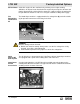


LTW 20Z Schematics
wc_tx001064gb.fm
7 9
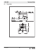
7.2 LTW 20Z-1—Electrical Schematic Components
Ref. Description Ref. Description
a Generator o Receptacle, 120/240V 30 Amp
b Generator junction box p Circuit breaker, 240V 30 Amp
c Voltage regulator q Receptacle, 120/240V 50 Amp
d Exciter r Circuit breaker, 240V 50 Amp
e Stator (aux winding) s Control box
f Stator (main winding) t Terminal strip
g Circuit breaker, 120V 15 Amp u Control box ground
h Control box front panel v Transformer
j Engine controller w Capacitor
k Main breaker, 80 Amp x Lights
l Receptacle box y Fuse, 120V 2 Amp
m Receptacle, 120V 20 Amp GFCI z Generator connection block
n Circuit breaker, 120V 20 Amp — —