
User`s manual

VIA 693/693A AT MAINBOARD HARDWARE SETUP
3-13
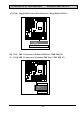
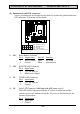
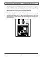
SPK: Speaker connector
1Pin #
Signal name
1 + 5V DC
2 Speaker Data Signal
3 Speaker Data Signal
4 Speaker Data Signal
5 No Connection
5
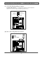
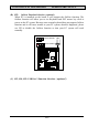
PWR-LED & KBLOCK: Panel Power LED and Key-Lock Connector
1Pin #
Signal name
1 Pullup (+ 5V DC for Power LED)
2 Ground
3 Ground
4 Keyboard Lock
5 Ground
5
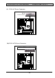
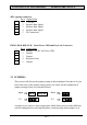
3.3 JUMPERS
This section will discuss the jumper setting on this mainboard. In order to let you
have better idea of the jumper setting, please see below for the explanation of
jumper settings before you start this section.
open
1-2
1
2-3
1
1
11
short
,
,
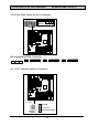
A jumper is two, three or more jumper pins which allows users to make different
system configuration by moving the plastic connector plug (mini-jumper) on it.