
Installation Guide

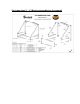


STEP9: Additional parts Hypotenuse (CNC) and Wall Supports or Projection
Bar Assembly (CNPM) are provided for extra support
STEP 10: Install additional (CNC) to complete the frame assembly
STEP 11: Wall Supports or Projection Bar Assembly (CNPM) are installed only if
needed after the Awning is hung on the wall
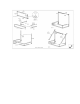
INSTALLING THE COVER
STEP 12: Slide the bead at the top of the fabric into the C-Channel at the top of
(TB).
STEP 13: Pull the remainder of fabric over the frame with the valance hanging
down below the (CNC) and (FB) bars.
STEP 14: Once you are satisfied with the position of the cover on the frame,
wrap the Velcro strips on the fabric tabs around the exterior bars. Pull the tabs
snugly and attach them to the pre-installed Velcro tape on the bars.
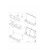
POSITIONING THE BRACKETS CORRECTLY ON THE WALL
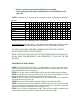
*** all the sizes are in inches
Model
Space
between
TB and
BP
Height
incl
valance Projection
RN22 31 31 24
CN32 44 44 24
CN33 44 44 36
CN34 44 44 48
CN43 56 56 36
CN44 56 56 48
EN2442 24 24 42
EN12 12 12 24
EN1836 18 18 36
EN1230 12 12 30
EN1030 16 16 30
EN23 24 24 36
EN24 24 24 48
STEP 13: Place the awning on the wall and make adjustments to choose the ideal
location. Mark the bottom of the frame after you have centered it on the opening
that you are covering.
STEP 14: Using a pencil and a level, mark a horizontal line as wide as your
awning at that height. Verify that it is centered on the space.
STEP 15: From the inside of the awning, make (2) marks on the wall 6” up from
that line where the awning frame touches the wall. . This is where the bottom of
the brackets will be placed.
STEP 16: From the inside of the awning, make two marks on the wall 6” in from
the top outside corners of the awning where the (CNB) and (TB) bars meet the