
Operating instructions

2-3
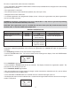
Information entered or calculated by the controller is stored in two different ways:
A static memory will store:
Media volume
Regenerant setting
Time of regeneration
Days between regeneration
A dynamic memory with 8 hour retention will store:
Current day of week
Running clock
NOTE: Water fl ow to the valve can be turned on or bypassed when the controller is powered up for the
fi rst time.
VARIABLE RESERVE FUNCTION
The AWS metered-demand volumetric controllers are designed to have a variable reserve feature. This feature
automatically adjusts the reserve to the end-user’s water usage schedule.
A variable reserve saves salt and water by only regenerating when absolutely necessary, and ensures enough
soft water for typical high-water usage days.
Each day of regeneration the controller reviews the last four weeks of water usage for the same day of the week
to determine if the remaining capacity is adequate for the next day of the week. If not, it will initiate an automatic
regeneration.
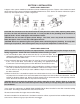
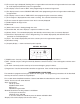
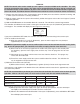
DISPLAY ICONS
NOTE: In normal operation and during programming, only a few of the icons will actually be displayed.
1) Days of the week. The fl ag immediately below the day will appear when that day has been programmed as a
day the system should regenerated (used with 7-day timer programming).
2) See #3
3) This cursor is displayed when the days between regeneration are being programmed (used with .5 to 99 day
regeneration programming).
4) One of these cursors will be displayed to indicate which day will be programmed into the controller
5) “PM” indicates that the time displayed is between 12:00 noon and 12:00 midnight (there is no AM indicator).
PM indicator is not used if clock mode is set to 24-hour.
6) When “MIN” is displayed, the value entered is in minutes increments.
7) When “LBS” is displayed, the value entered is in pounds.
8) When “Kg” is displayed, the value entered is in kilograms or kilograins.
9) Four digits used to display the time or program value. Also used for error codes.
10) Colon fl ashes as part of the time display. Indicates normal operation.
11) Locked/unlocked indicator. In Level I programming this is displayed when the current parameter is locked-
out. It is also used in Level II programming to indicate if the displayed parameter will be locked (icon will fl ash)
when controller is in Level I.
12) When “x2” is displayed, a second regeneration has been called for.