– the advantage is yours Assembly and operating Instruction www.ax-lightness.de www.engage-bikes.
1 Some notes on this manual Particular attention should be paid to the following symbols: symbol indicates an imminent risk gThis to your life or health unless you comply with the instructions given or take preventive measures. a This symbol warns you of wrongdoings which may result in damage to property and environment. symbol marks information about iThis how to handle the product or refers to a passage in the operating instructions that is particularly relevant.
2 3 Dear AX-Lightness and engage customer, Congratulations for having purchased an AXLightness or engage component. You have made a very good choice. The AX-Lightness and engage team develops, tests and manufactures our products with dedication to uphold the highest standards of quality. General safety notes Like all high-quality sports equipment, AX-Lightness and engage components require careful installation and are best left to an AX-Lightness and engage dealer.
5 Before your first ride – Intended use AX-Lightness and engage brakes and brake pads, rims, rim tape and wheels, quick-releases, forks and headsets, cranksets, pedals, handlebars and stems (a) as well as seat posts and saddles (b) are designed for use on road and triathlon (i.e. time trial), cyclocross and mountain bikes and their typical use. a Road racing, triathlon and time trial bicycles are exclusively designed for cycling on tarred and hard-surface tracks with a smooth surface.
6 7 Before every ride Check the following points before setting off on your AX-Lightness and engage bicycle: a 1. Verify the tight fit of the stem on the fork steerer and of the handlebars in the stem. For more information see chapters “Mounting AX-Lightness and engage Aheadset®-stems” and “Mounting AX-Lightness and engage handlebars”. 2.
8 9 on fast and steep descents can gBraking cause your wheels to heat up, possibly damaging the tyres, tubes and rims. In the worst case this can result in a sudden loss of air and thus in a serious accident. Get used to proper braking and let the brakes cool down from time to time.
10 11 Components made of carbon have like all lightweight components only a limited service life. Therefore, to be on the safe side it is recommended that you replace AX-Lightness (a) and engage handlebars, stems and headsets depending on use at regular intervals (e.g. every three years), even if they were not involved in an accident or similar incident.
12 13 Maintenance Check the true running of the rims, the bolts of the sprocket assemblies and the play of the bearings after the first 100 to 300 km (60 to 180 miles) and true the AX-Lightness and engage wheels (a) and/or adjust the bearings, if necessary. a b c Check the torque values of all bolts (b) after the first 100 to 300 km (60 to 180 miles) or 10 to 20 hours of use.
14 15 a Before installation watch out for sharp edges and burrs in the seat tube of the frame (a), at the seat post clamp and the saddle clamping, in all clamping areas of the fork, the headset, the stem, the handlebars and, if necessary, on the handlebars approved for bar ends. Do not use these components, if they have burrs or sharp edges. Have components from any manufacturer with sharp edges or burrs checked by your AXLightness and engage dealer.
16 17 A note on wear Bicycles components are subject to wear due to normal and proper use. The wearing rate depends on care and maintenance, bicycle usage and environmental conditions, such as UV light, rain, mud, dust, and sand. a b c d Some AX-Lightness and engage components require regular care and maintenance. But even with the best maintenance all components will reach sooner or later the end of their service life, depending on the intensity and the conditions of use.
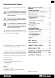
18 76 Brakes 19 Handlebars - Stem Rims - Wheels 34 Framesets - Assembly instructions 104 Fork - Headset 65 Seat posts - Saddles Brakes Framesets Seat posts - Saddles 112 Handlebars - Stem Crank systems - Pedals Fork - Headset 85 Brakes Crank systems - Pedals Rims - Wheels This user manual is sub-divided into “component chapters” referring to the AX-Lightness and engage components. This user manual has edge indices which help you to quickly find the desired chapter.
20 21 Compatibility. . . . . . . . . . . . . . . . . . . . . . . . . . . . . . . . . . . . . . . . . . . . . . . . . . . . . . . . . . . . . 22 Operation and wear. . . . . . . . . . . . . . . . . . . . . . . . . . . . . . . . . . . . . . . . . . . . . . . 24 Functional check. . . . . . . . . . . . . . . . . . . . . . . . . . . . . . . . . . . . . . . . . . . . . . . . . . . . . . . . . . 24 Brake adjustment and maintenance. . . . . . . . . . . .
23 a G Wet weather reduces your braking power and the road grip of the tyres. Wet weather reduces your braking power and the road grip of the tyres. AX-Lightness and engage recommend that you use high-end brake cables of one of the leading suppliers. It is recommendable to use the brake cables delivered with your brake levers. G Ensure that braking surfaces and brake pads are absolutely free of wax, grease and oil (a).
24 25 a Actuating the levers on the handlebars (a) and the cables causes a brake pad to be pressed against a braking surface (b+c), and the ensuing friction slows down the wheel. If water, dirt or oil comes into contact with one of the braking surfaces, this changes the coefficient of friction and deceleration is reduced. This is why brakes respond with a slight delay and less powerfully in wet weather.
26 27 Synchronising and readjusting the brakes To adjust the brake pads in parallel to the braking surfaces of the rims, place a flat 12 mm open-ended wrench to the wrench surfaces directly behind the brake arms (a). a b The position of the brake lever where the brake starts to act, also referred to as pressure point (c), can be adjusted to the size of the hand as well as to individual convenience by readjusting the brake cable.
29 Replacing brake pads a For dismounting the brake pads unscrew the adjusting nut of the re-tensioning unit at the AX-Lightness and engage brake calliper. Relieve the brake calliper, by pressing together both brake arms with one hand and unhooking the entire brake cable fixing with the other hand (a), as you usually do when dismounting a wheel. If you have Campagnolo brake lever/shifter units, you can slacken even more at the lever (b). Release the brake pad bolts.
30 31 Mounting brakes and brake cables rear Bowden cables transmit the rider’s signals between the brake levers/shifter units and the brakes. It is not least the net brake mounting and cable routing which makes for a perfect functioning of the brake. a Unscrew the sleeve nut from the brake fastening bolt. Slide the AX-Lightness and engage brake with the long bolt into the fork and that with the short one into the rear frame (a).
32 33 The outer housings are mounted to the brake lever/ shifter units and to the AX-Lightness and engage brake callipers with cable stops. a As a preventive measure for creaking noises and corrosion, apply a little grease to the cable stops and the counterbearing on the brake calliper. Grease the inner cables by pulling them through some bearing grease between thumb and index finger (b), while inserting the cables through the housings and the cable stops to the brakes.
34 35 Quick-releases. . . . . . . . . . . . . . . . . . . . . . . . . . . . . . . . . . . . . . . . . . . . . . . . . . . . . . . . . . . . 37 How to securely mount the wheel. . . . . . . . . . . . . . . . . . . . . . . . . . . . . . . . . . . . . . . . . 38 Thru axles. . . . . . . . . . . . . . . . . . . . . . . . . . . . . . . . . . . . . . . . . . . . . . . . . . . . . . . . . . . . . . . . . 39 Notes on how to mount rear wheels . . . . . . . . . . . . . . . . . . . . . . . . . . . . . . . . . . . . .
36 37 a The wheel consists of the hub, the spokes and the rim (a). The tyre is mounted onto the rim, either a tubular tyre that must be glued on the rim or a clincher or folding tyre which has an inner tube inside. There is a rim tape running around the rim well to protect the sensitive tube against the spoke nipples and the edges of the rim well, which are often sharp. A quick-release (b) or a thru axle connects the AXLightness and engage wheels with the frame and the fork.
39 How to securely mount the wheel Thru axles Open the quick-release (a). The marking “Open“ on the lever should become visible now. Thru axles (e) are mounted when bicycles have to withstand high stress occurring, e.g. in the case of mountain bikes. They provide suspension forks with a suitable stiffness. Make sure the component to be fastened is in the accurate position. a b Move the lever back, as if to close it. Now you should be able to read Ax and ”Close“ on the outside of the lever (b).
40 41 g Improperly mounted AX-Lightness and engage wheels may throw you off your bicycle or result in serious accidents! mount the axle only use the tools recoma Tomended by the manufacturer. Make it a rule b to use a torque wrench (a). Tighten carefully by approaching the prescribed maximum torque in small steps (0.5 Nm increments) and check in between the proper fit of the component.
42 43 Besides the front thru axle systems, there are also rear thru axle systems (a). This system combines extreme stiffness with light weight. a To remove the rear wheel release the axle (with an Allen key or the RWS lever, depending on the system) and pull it out, before removing the rear wheel in the usual way. Make sure not to insert the axle (b) into the hub before mounting the rear wheel. Perform the rear wheel mounting in the usual manner.
45 psi bar psi bar psi bar 30 2.1 70 4.8 110 7.6 40 2.8 80 5.5 120 8.3 50 3.5 90 6.2 130 9.0 60 4.2 100 6.9 140 9.7 with too low pressure can lead to a Riding bottom out resulting in a crack or breakage of the carbon rim. G Clincher, folding and tubeless tyres allowing an inflation pressure of 5 bars or more have to be mounted on hook bead rims, identifiable by the designation “C“. If you are in doubt or if you have any questions, contact your AX-Lightness and engage dealer.
47 a Rim trueness and spoke tension Wheel removal For the true running of the wheel it is imperative that the tension exerted by the spokes is distributed evenly around the rim (a+b). If the tension of a single spoke changes, e.g. as a result of riding fast over a kerb or of a loose nipple, the tensile forces acting on the rim become unbalanced and the wheel will no longer run true.
49 Wheel mounting (mountain bike/road racing bicycle) Make sure the wheel is correctly seated in the dropouts and accurately centred between the fork legs or the seat and chain stays. Make sure the quick-release (a) and the drop-out safety tabs are correctly seated. For more information see chapter “Quick-releases”.
51 a b Tubular tyres Tyre removal To ensure a durable fit, a tubular tyre needs to be mounted carefully. The mounting needs to be carried out in several steps and may require a little time. A little practice and experience with the glue you are using and the respective tubular model can speed up the job. To remove the tyre, start opposite the valve by pushing the tyre to the centre of the rim until there is a gap and the tyre starts to come off (b).
52 53 a b With liquid tyre glue you need several layers to create a well-adhesive base. Spread the tyre glue evenly and in very thin layers over the entire rim. With a little practice you will be able to apply the glue straight from the tube. But you can also use a stiff brush (b). When using tyre glue in tins, you need a brush in any case. Allow the tyre glue to dry until a finger test will proof that it is tacky-dry. This can take several hours.
55 a I When mounting a tyre on a rim that has already been used, it may be necessary to remove glue residues and dirt with a steel brush or with emery cloth (a). When you are done, wipe the rim with a soft rag and acetone or benzine. I There is special tubular tyre cement (e.g. from Continental) for carbon rims. Before using this type of glue, read the operating instructions. I Observe the video showing the secure gluing of Continental tubular tyres on carbon rims at www.conti-online.
56 57 To finish mounting the tyre, start at the opposite side of the valve. Use your thumbs to press the other tyre bead over the rim flange as far as you can. a Make sure the inner tube does not get pinched and squashed between the tyre and the rim. You can prevent this by pushing the inner tube into the hollow of the tyre (b) with a finger as you work along. Work the tyre into the rim by approaching the valve symmetrically from both sides.
58 59 a » The nipples of AX-Lightness and engage wheels that were in use for a rather long period of time may “cling” to the spokes. It is advisable to start with slightly releasing the nipples, i.e. by a quarter turn, before you tighten them, to prevent the spokes from being turned off during re-truing. from AX-Lightness and engage recoma We mend that you have your wheels trued up solely by an AX-Lightness and engage dealer. Inappropriately tightened spokes can cause irreparable damage.
60 61 a Please make sure the limit stops are properly adjusted. An inappropriate adjustment can lead to a failure of the drive or make the rear derailleur collide with the spokes – this can damage your bicycle or even result in an accident! A The lock nut of the sprocket assembly must engage four full turns at least, otherwise there is the risk that the drive is damaged. G Check the functioning of the gears after the reassembly of the sprocket assembly (a).
62 63 I a If the bolts are to be re-used after dismounting, they need to be treated with another coat of retaining compound! Also observe the general bicycle user manual of the bicycle manufacturer as well as the chapter “The brake system” of the present user manual. If you have any questions, contact your AX-Lightness and engage dealer or our service centre.
64 65 What to bear in mind with rim brakes Please note, if you have rim brakes, that the braking effect (a) is also greatly reduced in wet conditions. It may take some time until the brake responds. Let the brake drag before the actual braking manoeuvre to get the rim dry. Be particularly cautious when riding on wet or dirty roads and do not ride as fast as you would in dry conditions to have more time for braking.
66 67 What to bear in mind with carbon steerer forks. . . . . . . . . . . . . . . . . . . . . . . . . . . . 67 Mounting forks with threadless carbon steerer. . . . . . . . . . . . . . . . . . . . . . . . . . . . 68 Headset. . . . . . . . . . . . . . . . . . . . . . . . . . . . . . . . . . . . . . . . . . . . . . . . . . . . . . . . . . . 72 General notes on mounting and compatibility . . . . . . . . . . . . . . . . . . . . . . . . . . . .
68 69 The outer surface of the sleeve must remain free of grease. Apply AX-Lightness carbon assembly paste in this area, as well, before tightening the mechanism in the fork steerer. Measure the crown race (b) and the fork crown (c) first. Forks with 1 1/8”- steerer tubes (steerer tube diameter 28.6 mm) require crown races at a nominal diameter of 30.0 mm. AX-Lightness forks in combination with AX-Lightness stems can also be used without expander.
70 71 a Use a sharp, fine-toothed metal saw (24 teeth) (b) and cut the fork steerer at low pressure 2 mm below your marking (c). Make sure to keep the inner steerer tube free of chips and dust. Do not blow off the saw chips. Remove the chips with a damp rag (d) and dispose of them together with the rag! Use a file with fine teeth to gently remove any burrs from the area of the cut (e). Insert the file from the outside to the inside (f) and not vice versa, otherwise the fibres will fray out.
72 73 General notes on mounting and compatibility a b c The headset connects the AX-Lightness and engage fork to the frame, but allows it to move freely (a). It must turn with virtually no resistance, if the bicycle is to run straight, stabilising itself as it travels. Shocks caused by uneven road surfaces expose the headset to considerable levels of stress. In this way it can become loose and go out of correct adjustment.
74 75 The maintenance of the headset, the removal of noises in spite of correct adjustment or an insufficient steering behaviour require a dismounting of the AXLightness and engage fork from the frame. a The maintenance of the AX-Lightness and engage headset is a job for a skilled bicycle mechanic. Have this work solely done by an authorized AX-Lightness and engage dealer. If you want to try it on your own, you should have the know-how and experience of a mechanic as well as special tools, e.g.
76 77 General notes on mounting and compatibility . . . . . . . . . . . . . . . . . . . . . . . . . . . . 78 Mounting the chainrings. . . . . . . . . . . . . . . . . . . . . . . . . . . . . . . . . . . . . . . . . . . . . . . . . . 79 Mounting the cranks in all bottom brackets. . . . . . . . . . . . . . . . . . . . . . . . . . . . . . . 80 Mounting the bottom brackets in BSA or BSC bottom bracket shells. . . . . . . 81 Dismounting the cranks. . . . . . . . . . . . . . . . . . . . . . . . . . . . . . .
78 79 Mounting the chainrings General notes on mounting and compatibility AX-Lightness cranks are delivered without chainrings, which allows you to determine the number of teeth and the colour you want. If you want to mount chainrings, contact your AX-Lightness and engage dealer. He will procure you the matching components. Due to the huge number of frame standards, mounting a crank system (a-d) into a bicycle frame is a job for a skilled mechanic.
80 81 AX-Lightness cranks can be mounted with the standard shaft into the BB 386 Evo bottom bracket shell. (e) and pre-mount the left crank, as described. Care- With a special shaft, they can also be mounted in standard BB 30 shells. fully check whether the cranks are freely movable and make sure they do not collide with another component.
82 83 AX-Lightness cranks are fitted with an integrated extractor tool. For this reason the dismounting does not require an additional special tool. Approach a long Allen key and release the bolts anticlockwise (a). a Once the bolt is loose, you can turn it a few rotations without feeling hardly any resistance, before it comes to a stop at the outer crank cap and the resistance increases from this point on. Continue turning by applying force. The crank will then loosen from the shaft.
84 85 Mounting the pedals Apply high-quality mounting grease to the threads in the crank arms, the pedal threads (a) as well as to the contact surface of the pedal axles. a Handlebars – Stem Position the axle of the right pedal with your fingers and screw it in clockwise by a few turns (b), before tightening it with a pedal wrench (c) or a long 15 mm open-ended wrench. The left pedal has a left-hand thread. Position the axle also with your fingers and screw it in anticlockwise.
86 87 85 87 88 90 93 95 97 General notes on mounting and compatibility Before you start mounting make sure the stem you have chosen has a clamping diameter matching the AX-Lightness and engage handlebars. The same applies to both the stem and the steerer tube. Adjusting the handlebar height . . . . . . . . . . . . . . . . . . . . . . . . . . . . . . . . . . 100 Our AX-Lightness road racing handlebars have a clamp diameter of 26.0 mm. Aheadset®-stems. . . . . . . . . .
88 89 Many AX-Lightness (a) and engage stems can be mounted in either vertical orientation. These flip-flop models allow handlebars to be positioned at two different heights by simply inverting the stem. a Make sure the AX-Lightness and engage stem and fork steerer tube always have matching or compatible clamp diameters (b)! If you fit a new AX-Lightness and engage stem on a fork with carbon steerer tube, check the clamping area of the fork for notches or abrasion marks.
90 91 Apply AX-Lightness carbon assembly paste in the area of the clamping (a+b) on the AX-Lightness and engage handlebars as well as on the stem. a b Position the stem clamp in the middle of your new AX-Lightness and engage handlebars (c) so that the handlebars extend the same distance from the stem on each side. If the handlebars do not slide easily into the stem clamp or if there is play between the two components, ask your AX-Lightness and engage dealer whether both components are compatible.
92 93 Carefully slide the clamp on the handlebars (b) and subsequently re-mount the unit to the clamp. a Start tightening the clamping bolts slightly, so that the unit can still rotate freely. Bring the brake lever/ shifter units to the desired position. As soon as the unit is in the desired position, apply some AX-Lightness carbon assembly paste in the area of the clamping. b c Adjusting the Aheadset®-headset Adjusting the headset is a job for a skilled bicycle mechanic.
94 95 a Be sure to observe the chapter “Fork – Headset” or the instructions given in the user manual of the fork manufacturer before tightening the stem. Start by tightening both clamping bolts alternately and then by using a high-quality torque wrench (a). Start with a standard torque wrench and a minimum torque value of 3 Nm. Check the secure clamping of the AX-Lightness and engage stem by holding the front wheel between your knees and trying to turn the handlebars relative to the front wheel (b).
96 97 In case the handlebars are not tight, check that each bolt was tightened to the recommended torque value (4 Nm for AX-Lightness stem clamping bolts) (a). If each bolt was tightened to a torque value of 4 Nm and the clamping force is still insufficient, release the bolts, remove the handlebars from the stem and apply another coat of AX-Lightness carbon assembly paste to the clamping areas (b). a Retighten each bolt individually (c) to a torque value of 4 Nm.
98 99 a Check that the clamping areas of the bar ends are free of burrs and sharp edges. Do not use bar ends with burrs or sharp edges. Burrs are sharp and can cut into other components. If there are any burrs or sharp edges, contact your AX-Lightness and engage dealer. Replace the bar ends by models that are free of burrs.
100 101 a Both the handlebar height and the stem length determine how much your upper body will be inclined forward. Lowering the AX-Lightness and engage handlebars gives the rider a streamlined position and brings more weight to bear on the front wheel. An excessively low handlebar position may prove uncomfortable and can strain wrists, arms, upper body and neck. Seek the assistance of a qualified AX-Lightness and engage dealer, especially if you experience pain or discomfort after set up and use.
102 103 Grips (a) and bar tapes (b) not only provide comfort, but also have a very important secondary function: they ensure that your hands’ movements communicate clearly with the steering components. a Make sure the grips and the bar tape are in good, functional condition. Replace worn through or extremely dirty grips and bar tapes immediately. At least once a year it is time for them to be checked or replaced.
104 105 FRAMESETS – ASSEMBLY INSTRUCTIONS AND TECHNICAL DATA. . . . . . . . . . . . . . . . . . . . . . . . . . . . . . . . . . . . . . . . . . . . . . . . 104 General notes on mounting and compatibility. . . . . . . . . . . . . . . . . . . . 106 Technical data – Connecting dimensions – Torque values. . . . . . . . .
106 107 AX-Lightness and engage offer the high-quality carbon framesets (a+b) as bare frames for individual fitting with components. a The person completing and mounting the add-on parts must therefore ensure that all components are compatible and properly mounted (c+d). There is a vast variety of available add-on parts, making it impossible for AX-Lightness and engage to cover every conceivable option in this manual.
108 109 a A b I c Whoever assembles an AX-Lightness and engage bicycle frame from a bare frame carries the responsibility for ensuring that the components are selected and mounted in accordance with the manufacturers’ guidelines, generally accepted standards and the state-of-the-art in science and technology.
110 111 a b Seat post AX-Lightness and engage recommend using frames with AX-Lightness or engage seat posts (a). The components fit and function as integrated whole and will allow you to achieve optimum performance. In case you want to mount the seat post of another manufacturer after all, make sure it has the same nominal diameter as the frame’s seat tube (b). You should be able to slide the seat post easily into the frame without pressing or turning.
112 113 General notes on mounting. . . . . . . . . . . . . . . . . . . . . . . . . . . . . . . . . . . . . . . . . . . . . . 114 Saddles . . . . . . . . . . . . . . . . . . . . . . . . . . . . . . . . . . . . . . . . . . . . . . . . . . . . . . . . . . 116 Mounting the saddle on the seat post. . . . . . . . . . . . . . . . . . . . . . . . . . . . . . . . . . . . 117 Rider-specific adjustments . . . . . . . . . . . . . . . . . . .
114 115 General notes on mounting Make sure your new AX-Lightness and engage seat post has the same diameter as the seat tube of your frame. a The AX-Lightness seat post Europa (a) is available with the nominal diameters: 27.2 mm, 30.9 mm, 31.6 mm and 34.
116 117 Mounting the saddle on the seat post The product range of AX-Lightness and engage comprises a variety of saddle models (a+b) which not only differ in weight, but also in terms of spring properties and proper fit. Your AX-Lightness and engage seat post is designed for most sport saddles with a saddle rail diameter of 7 mm as well as for saddles with slightly ovalized saddle rail tubes (width 7 mm and height 9 mm) including AX-Lightness and engage saddles.
118 119 a In the case of the cranked AX-Lightness and engage seat posts, turn the bolt in the front either gradually by hand (b) or remove the AX-Lightness and engage seat post from the frame and insert a long 5 mm Allen key from the bottom and tighten the bolt. Once the crossmember engages with the rail, pull the saddle upward and tighten the bolt. Tighten the front bolt by two to three turns more to lower the saddle nose a little.
120 121 Adjusting the correct saddle height a b To adjust the saddle height loosen the binder bolt (a) or quick-release lever (read the chapter “How to use quick-releases of seat post clamps“ beforehand). Release the seat post binder bolt by using a suitable tool and turn it anticlockwise by two to three turns or open the quick-release at your saddle clamping. You can now adjust the AX-Lightness and engage seat post to the desired height.
122 123 When the ball of your foot is exactly above the pedal centre in the ideal pedalling position, your knee should be slightly bent (a). If it is, you have adjusted the saddle height correctly. a Check whether you can balance safely on your bicycle while sitting on the saddle by stretching your feet to the ground. If you cannot, you should lower the saddle a little, at least to begin with.
124 125 a Tighten both bolts evenly so the saddle remains at the same angle. If you wish to lower the nose of the saddle a little, tighten the front bolt clockwise. If necessary, you may have to loosen the rear bolt a little as well. To lower the rear part of the saddle, the rear bolt has to be tightened clockwise and the front bolt to be released, if necessary.
126 127 Make sure the lever is fully closed. Only in this position maximum hold is achieved and it is ensured that the quick-release remains closed. In its end position, the lever should be parallel to the bicycle (a), i.e. it should not stick out. The lever must lie close to the frame so that it cannot be opened accidentally. a Finish by checking the firm hold of the saddle by taking hold of the saddle and trying to rotate it in the seat post (b).