
User's Manual Part 2


The circuitry of the IF Processor Module goes through the following stages as described in
the text that follows.
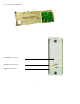
Impedance Matching and Gain Selection Circuitry
The IF input signal is applied from the backplane connection to J1-32B, the DIN connector
located at the back of the module. An input impedance transformer can be set to 50Ω or
75Ω using jumper J28 and J29. The input range is selected with the I/P gain jumpers J8,
J9, J10, and J11.
37
Gain Jumper Setting Input Range
HI Gain -22 to -12 dBm PEP
MED Gain -17 to -7 dBm PEP
LO Gain -12 to -2 dBm PEP