
User's Manual Part 2
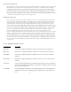


Input Signal Detection Circuitry
A sample of the IF input signal that is taken through a directional coupler after passing
through the impedance matching and gain circuitry, is applied to an envelope detector. The
average and peak amplitudes of the envelope are measured and sent to a set of comparator
circuits. These circuits will detect the following fault conditions if present.
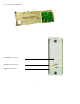
Frequency Response Equalization Circuitry
Placing jumper J2 and J3 to the IN position will form a four point frequency response equal
ization circuit in the IF path to offset any frequency response in the system.
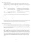
Output Signal Detection Circuitry
Analog DC signals relating the level of output power generated by the power amplification
stages of the system provide feedback to the ALC circuit. These signals are applied to the IF
processing module through DIN connectors J1-24C INNER LOOP IN and J1-25C OUTER
LOOP IN. Next, the signals are processed through the output signal detection circuitry before
being applied to the ALC circuit.
The inner loop signal is a DC voltage that originates from within the unit that contains the IF
processing module and represents the level of RF output power generated from the PA stages
of the unit. The optional outer loop signal is a DC voltage generated from outside the unit
and represents the level of RF output power generated from an external amplifier. For both
signals 1 volt equals 100% output power. The output signal detection circuit selects one of
these signals and applies it to the ALC circuit. If the outer loop signal is greater than 90% it
will be selected, otherwise the inner loop signal will be selected. Both signals are buffered
and sent back out of the module through DIN connectors J1-23C and J1-26C. Test point
TP5 loop voltage is used to measure the level of the loop signal being applied to the ALC
circuit.
The peak vs average fault condition can be enabled or disabled with jumper J30 on the
module
38
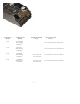
Fault Condition Action
Input Fault The peak level of the input signal When the module is in ALC mode set the input fault line
drops below the specified I/P range J1-8C to logic low and mute ALC circuitry. Illuminate RED
I/P fault LED
Peak vs The average level of the input signal is Set the peak vs average line to logic low and mute the ALC
Average Fault 1dB or less below the peak level of the curcuitry. Illuminate RED P/A fault LED.
input signal