
User's Manual


This module consists of the A1, LO/ Upconverter board, a channel filter, and an output
amplifier board. This module takes an external IF and converts it to the final RF output
frequency using an internally generated local oscillator.
The local oscillator consists of a VCO that is phase locked to an external 10 MHz reference.
The 10 MHz reference and the VCO are both divided down to 500kHz and compared by the
phase lock loop. Error signal from this comparison is generated in the form of an error cur
rent that is converted to a bias voltage to the VCO. This voltage adjusts the output fre
quency of the VCO until it is on the desired frequency.
Phase lock loop is programmed by loading in data generated by the control module . This
data sets the dividers so that the 10MHz and the VCO frequency are divided to 500kHz.
These divide numbers are loaded into U6 using the clock, data and LE lines. This data is
sent whenever the module is first plugged into the back plain or when power is applied to the
tray. This is necessary because the divide numbers are lost when power is removed from the
module.
There is an alarm generated if the phase locked loop is unlocked. This alarm is displayed
locally and is also sent to the control module in the transmitter to be displayed as a fault.
The bias voltage to the VCO is also available to be monitored at TP1 and also can be viewed
an the transmitter front panel display. Normal values for this voltage are 0.5 to 5V.
The 10 MHz reference is normally an external reference. There is also a high stability inter
nal reference option that is available if there is a desire to operate the transmitter without
an external reference. Jumper W1 determines whether an external or internal high stability
reference is to be used.
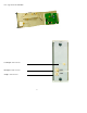
The IF signal is applied at a level of -5dbm peak sync plus sound and is converted to the
final RF channel frequency. The RF signal is applied to a filter that selects the right conver
sion product. Next, the signal is amplified to -7 dBm by A3 and exits the front of the module
at J2. There is also a front panel sample of the RF output , J3, and the LO, J1. The RF
sample level is approximately -20 dB below the RF output. The LO sample level is -13 dBm.
Jumpers
35
J2 Internal / external 10 MHz reference internal 2,3
external 1,2
J4 Setup / operate to set L.O. oscillator frequency operate 1,2
works with R10 setup frequency adjustment setup 2,3