
User's Manual Part 1


Axcera • 103 Freedom Drive • P.O. Box 525 • Lawrence, PA 15055-0525 USA • 724-873-8100 • FAX 724-873-
8105
info@axcera.com • www.axcera.com
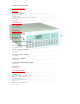
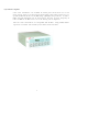
5720 Series
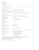
Specifications
Subject to change without notice
5721 5722 5723 5724 5725 5726 5727
Inputs / Connectors ................... Video Input / BNC; Baseband Audio Input / Screw Terminals; Composite
Audio Input / BNC; Visual IF
Input / BNC; Aural IF Input / BNC; IF Input / BNC; 10 MHz Ref Input / BNC;
IF CW Input / BNC; Remote Interface / D; Control Interface / D; SCADA / RJ45 (2 connectors)
Outputs / Connectors ................. RF Output / N; Visual IF Output / BNC; Aural IF Output / BNC; Combined IF
Output / BNC; RF Sample /
SMA; LO Sample / SMA; IF Sample / SMA (2 connectors)
Operational Temperature Range
7
. 0°C to 45°C
Specified Temperature Range
7
..... 15° C to 35° C
Relative Humidity ....................... 0 to 95% non-condensing
Dimensions (W x D x H) 19” x 21” x 7” 19” x 21” 19” x 21”
(48.3 cm x 53.3 cm x 17.8 cm) x 12.25” x
17.5”
(48.3cm x 53.3cm (48.3cm x 53.3cm
x 31.1cm) x 39.4cm)
Line Voltage
8
......................................... 117-240 VAC ±10%, 50/60Hz
Power Consumption (Watts) 250 380 380 520 875 1500 2880
Power Consumption (VA) 260 390 390 530 940 1620 3110
Weight 45 lbs. (20 kgs.) 100 lbs. 125 lbs. 165 lbs.
(45 kgs.) (57 kgs.) (75 kgs.)
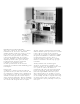
Monitoring
Front Panel ........................................... Front panel LCD/keypad displays forward power, reflected power,
RF channel, ALC voltage,
AFC voltage, IF input status, output power status, PLL locked
status, external reference present status, amplifier module status, temperature fault
status, power supply
status, external amplifier module status, external amplifier tem-
perature status, external amplifier power supply status, internal modulator PLL status,
internal modulator input status; operate and fault LED indicators
SCADA .................................................. SNMP network management system for remote control and moni-
toring of output power,
status, and operating mode via modem or LAN/WAN
7. RF performance specifications guaranteed over specified temperature range. Units will run reliably over opera-
tional temperature range but may deviate from specifications. Derate maximum operational temperature by 2° C
per 1000 feet above sea level.
8. Amplifier trays for models 5725, 5726, 5727 require 208/240 VAC ± 10% 50/60 Hz line voltage.
Digital / Analog
MMDS Transmitter
Ordering Information
5721 10/2.5W peak/avg. transmitter
5722 20/5 W peak/avg. transmitter
5723 30/10 W peak/avg. transmitter
5724 50/15 W peak/avg. transmitter
5725 100/25W peak/avg. transmitter
5726 160/50 W peak/avg. transmitter
5727 280/100 W peak/avg. transmitter
Options
NTSC/PAL modulator module for analog applica-
tions
LPN oscillator module for digital applications
Internal reference oscillator
5040 VHF/UHF Receiver