
User Manual


ADCP-62-504 • Issue 1 • November 2000 • Section 1: Introduction
Page 1-6
2000, ADC Telecommunications, Inc.
Through the EMS, the network administrator can manage and monitor both the base
station/hub devices and the WMUs located at the subscriber premise. The client/server
architecture of the EMS provides the facilities to manage the system from various locations
over the Internet. Because the Axity EMS provides this user-friendly Web interface,
technicians attempting to troubleshoot problems at remote locations can easily access network
management data and interfaces necessary to perform their tasks.
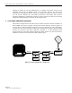
5 CUSTOMER PREMISE EQUIPMENT
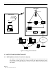
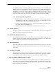
The hardware configuration for the CPE consists of outdoor transverter/antenna assemblies, an
indoor WMU, indoor power supplies, and associated coaxial cabling as shown in Figure 1-2
for the single user CPE configuration and Figure 1-3 for the multiple user CPE configuration.
A single coax interconnect provides the DC and IF (intermediate frequency) signal handling
between the transverter and indoor equipment. Typically, a 17 dBi integrated planar
antenna/transverter will provide sufficient signal gain. Other antennas can also be used with a
standalone transverter for locations that require a different gain.
IF DC + IF
Ethernet
Transverter
WMU
Power
Inserter
AC
Transformer
AC/DC
Converter
RF
NIC Card
Figure 1-2. CPE Configuration – Single User