
User Manual


ADCP-62-504 • Issue 1 • November 2000 • Section 1: Introduction
Page 1-2
2000, ADC Telecommunications, Inc.
2 SYSTEM OVERVIEW
The high-speed Axity Broadband Wireless Access System is designed to allow business,
school, government and residential users to access private and public data networks over
wireless channels. The system provides high-speed connectivity over wireless RF networks to
and from a computer or LAN using packet-based, point-to-multipoint (PTMP) architecture.
Major applications are Internet access, transfer of multimedia, video conferencing, distance
learning, and remote control access.
The system configuration contains a number of base stations referred to as “hubs.” The
equipment specifications, cellularization approach, availability requirements, and propagation
conditions determine the coverage area served by a single hub. The coverage area radius, as
measured from the base station, ranges from 5 miles for mini-cell, sectorized deployments to
greater than 20 miles for single-hub super-cell systems.
The term “downstream” refers to the broadcast transmission of information from the base
station to subscriber(s). The term “upstream” refers to the transmission from subscribers to the
base station over a time division multiple access (TDMA) link. In TDMA systems, a single
upstream channel is shared by assigning subscribers specific time intervals for transmission.
The Wireless Modem Termination System (WMTS), located at the hub, controls the allocation
of upstream bandwidth.
Axity provides maximum coverage, capacity and reliability to users within a service area by
optimizing CPE and cell site RF configurations and leveraging key features such as selectable
modulation order, selectable symbol rates, and advanced wireless algorithms.
The Axity system offers selectable modulation in order to provide sufficient downstream link
budget margin above the system carrier-to-noise plus interference level (C/N+I). This allows
the Axity platform to address both long and short distances in either super-cell or mini-cell
configurations. Selectable modulation also allows Axity systems to operate on the borders
between sectors or cells where interference potential is high. The system employs 16 or 64
Quadrature Amplitude Modulation (QAM) or Quaternary Phase Shift Keying (QPSK)
modulation for the downstream and QPSK for the upstream.
In addition, selectable symbol rates in both the downstream and upstream enable the Axity
network planner to optimize the use of the available spectrum.
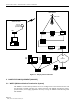
Figure 1-1 shows a typical configuration of the Axity system at the base station cell site and
the residential or business subscriber location. The system consists of a WMTS, a WMU
located at the customer premise, data networking equipment, the configuration, operating and
control software, and the interconnecting radio channel equipment.
The Axity system interfaces on the network side to various LAN or WAN connections
including Ethernet, DS3, OC3, etc., via a router. The subscriber’s PC interfaces to the WMU’s
10BaseT Ethernet port. The WMTS interfaces to the WMU over the wireless channel. This
wireless link allows the end user access to the service provider’s resources.
The base station RF equipment includes the RF transmitter and the downstream antenna
assembly, which transmits information from the WMTS to the subscriber WMU. From the
subscriber location, the upstream antenna/transverter and WMU receive information from the
subscriber location and pass it upstream through the WMTS to the network.