AX3000 Platine Terminal Ethernet TCP/IP Models 65B Installation Guide March 2004 - Ref: I65BE0303-1 Model AX3000/M65B
The reproduction of this material, in part or whole, is strictly prohibited. For additional information, please contact: 14 Avenue du Québec Bât. K2 EVOLIC - BP 728 91962 Courtabœuf cedex - FRANCE Tel.: 33 1.69.28.27.27 Fax: 33 1.69.28.82.04 Email: info@axel.com The information in this document is subject to change without notice. AXEL assumes no responsibility for any errors that may appear in this document. All trademarks and registered trademarks are the property of their respective holders.
1 - NOTICES ......................................................................................................1 1.1 - SAFETY NOTICES ................................................................................1 1.2 - EMC NOTICES ......................................................................................1 1.3 - PHYSICAL SPECIFICATIONS ..............................................................2 2 - INSTALLATION ............................................................................
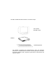
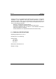
The AXEL AX3000 Terminal is based on a modular concept. VGA / SVGA standard monitor AX3000 standard keyboard The AX3000 is designed and manufactured by Axel. The terminal's electronics is contained within a slim base unit which provides connections for a VGA or SVGA monitor, keyboard, system printer, serial devices and Ethernet network.
Notices 1 - NOTICES 1.1 - SAFETY NOTICES y Do not attempt to fix a AX3000 component failure by opening the terminal case. In case of hardware failure, contact your service representative. y Check AC voltage from the wall outlet is inside 100-240 Volts range. y Make sure to use a properly grounded AC power outlet (3 poles: phase, neutral and ground with no resistance between neutral and ground pole).
Notices However, there is no guarantee that interference will not occur in a particular installation. If this equipment does cause harmful interference to radio or television reception, which can be determined by turning the equipment off and on, the user is encouraged to try to correct the interference by one or more of the following measures: - Reorient or relocate the receiving antenna. - Increase the separation between the equipment and receiver.
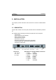
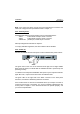
Installation 2 - INSTALLATION This chapter provides information and instructions to install the AX3000 Model 65B. 2.1 - DESCRIPTION A green LED, located on the face plate, indicates when the AX3000 is powered on.
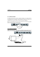
Installation 2.2 - INSTALLATION For safety reasons and to prevent component damage, do not apply power to the AX3000 before connecting or disconnecting any cable. Do not plug in the AX3000 power cord until all other connectors have been plugged in. Make sure the AX3000 and monitor power switches are in the OFF (0) position before connecting cables to the back panel. 2.2.
Installation If your keyboard is fitted with a DIN connector, connect it using a DIN-to-MiniDIN adaptor. Note: a serial mouse can also be connected to the AUX2 port. To comply with EMC regulations, the VGA signal cable must be shielded. Note: when the terminal is installed in a cabinet or rack, it is essential to maintain air circulation around the VGA/SVGA monitor. 2.2.
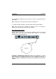
Installation Note: if the green LED does not light, check that the Ethernet connector and cable both comply with the specifications listed in chapter 4.1. 2.2.3 - Auxiliary Ports AX3000 Models 65B have three auxiliary ports as a standard feature: - AUX1: bi-directional serial port, RJ45 connector, - AUX2: bi-directional serial port, RJ45 connector, - PARALLEL: parallel port, female 25-pin connector. Cable pin assignments are listed in chapter 4.
Quick Installation 3 - QUICK INSTALLATION This chapter describes the quick set-up procedure for the TCP/IP Platine Terminal. The following command sequence is used to enter the AX3000 Set-Up: All the AX3000 set-up parameters (network environment, session settings and auxiliary port settings) can be adjusted through this set-up. For more information, refer to the guide: TCP/IP AX3000 - User's Manual. But, for a fast and reliable installation, the AX3000 provides a quick set-up function.
Quick Installation The quick set-up dialog box is displayed: Note: this box is automatically called when the AX3000 is powered up for the first time. Quick set-up parameters: - Keyboard: keyboard nationality. - Number of sessions: maximum number of sessions. These sessions are automatically associated with the host described above. - Configuration: virtual terminal settings. This choice is selected from a list. - Enable DHCP: two possible values: - yes: the DHCP protocol is run when the set-up is exited.
Quick Installation - Host IP address: if this field is left blank, DNS will be used to resolved the hostname. - Enable: Configuring printers attached to AX3000. If ‘Pre-defined Configuration’ is set to 5250 and a hostname is defined, PRT5250 (telnet printing) is automatically selected. If not LPD is the default printing system. This setting can easily be changed through interactive set-up. - Printer Name (accessible only if "Enable" is set): this is the printer name at the operating system level.
Connector Pin Assignments 4 - CONNECTOR PIN ASSIGNMENTS This chapter describes the connector pin assignments for the different ports of the AX3000 Models 65B. 4.1 - ETHERNET PORT RJ45 (LAN) Recommended wiring is a non-shielded twisted-pair cable (UTP), category 3 or 5 1 2 3 4 5 6 7 8 RJ45 connector (Models 65B rear panel) Note: the maximum length of a 10BaseT cable is 100 meters (330 feet).
Connector Pin Assignments b - AX3000 Connected to an Ethernet Controller Ethernet Board TX+ TXRX+ RX- AX3000 AX3000 ModelsModel 65B 55 1 2 3< 6< 1 2 >3 >6 TX+ TXRX+ RX- IMPORTANT: the cable is composed of two twisted pairs. The two wires TX+ / TX- must belong to one pair and the two wires RX+ / RX- must belong to the other pair. 4.
Connector Pin Assignments 4.2.1 - RJ45-DB9 and RJ45-DB25 adaptors Pin assignment for an adaptor between the peripheral cable and the AX3000 RJ45 connector: AX3000 - RJ45 DTR RD SG CTS TD 2 3< 4 5< 6 AX3000 - RJ45 DTR RD SG CTS TD 2 3< 4 5< 6 Adaptor - male 9-pin >4 2 5 8 >3 DTR RD SG CTS TD Adaptor - DTE female 25-pin > 20 3 7 5 >2 DTR RD SG CTS TD 4.2.
Connector Pin Assignments 4.3 - KEYBOARD INTERFACE The AX3000 keyboard interface is a Mini-DIN connector. To connect a keyboard which has a DIN connector, use a DIN-to-Mini-DIN adaptor: Pin 6 5 4 3 2 1 1 2 3 4 5 6 Signal name Data --Ground + 5 V DC Clock --- Keyboard connector (Models 65B rear panel) 4.
Connector Pin Assignments 4.5 - VIDEO INTERFACE The AX3000 video interface is VGA and SVGA compatible: 5 4 10 15 3 9 14 2 8 13 1 7 12 6 11 VGA/SVGA connector (Models 65B rear panel) Pin 1 2 3 4 5 6 7 8 9 10 11 12 13 14 15 14 Signal name Red Green Blue --Ground Ground Ground Ground Ground Ground ----Horizontal sync. Vertical sync.
Connector Pin Assignments 4.6 - PARALLEL INTERFACE The AX3000 Models 65B are equipped with a parallel port.
Problem Solving 5 - PROBLEM SOLVING This chapter describes some of the problems, that may occur during installation of the AX3000 Models 65B, and offers possible solutions. Safety Warning! Under no circumstances should you attempt to fix a Platine problem by opening the terminal case. High voltages may be present even when the terminal is switched off. Only qualified technicians should open the AX3000 case. 9 - THE VGA MONITOR VERTICAL SYNC IS LOST Care must be taken with the VGA monitor.
Problem Solving 9 - AFTER THE TERMINAL HAS BEEN SWITCHED ON, THE MESSAGES 'NO ETHERNET BOARD PRESENT' AND 'CANNOT ATTACH ETHERNET BOARD' APPEAR This message indicates a hardware failure. Report the problem to your service representative. 9 - A DOUBLE-BEEP SOUNDS After switching on the terminal, a double beep may sound, a few seconds after the normal first beep. This signal indicates that keyboard initialization has failed. Check the keyboard connection to the terminal back panel.
Problem Solving 9 - NO LOGIN WHEN THE 'CONNECTING...' MESSAGE IS DISPLAYED Check the Ethernet cables are correctly connected and networked devices (hubs or servers) are switched on. No connection (and no login) can also be due to a wrong terminal setting during the TCP/IP set-up (for example a wrong IP address). 9 - INCORRECT APPEARANCE OF SOFTWARE DISPLAYED ON THE AX3000 Check the values of parameters set using Terminal Set-Up. Check that the correct terminal emulation has been chosen.
14 Avenue du Québec Bât. K2 EVOLIC - BP 728 91962 Courtabœuf cedex - FRANCE Tel.: 33 1.69.28.27.27 Fax: 33 1.69.28.82.04 Email: info@axel.