
Installation guide


Connector Pin Assignments
Installation Guide - Models 65B 11
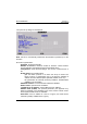
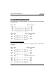
b - AX3000 Connected to an Ethernet Controller
2
3
2
3
6
TX+ 1 1
TX-
RX+
RX-
TX+
TX-
RX+
RX-6
<
<
>
>
AX3000 Model 55Ethernet Board
IMPORTANT: the cable is composed of two twisted pairs. The two wires
TX+ / TX- must belong to one pair and the two wires RX+ / RX- must
belong to the other pair.
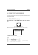
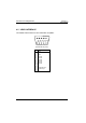
4.2 - SERIAL PORTS AUX1 AND AUX2 (RJ45)
These serial ports are bi-directional ports (for printers, bar-code readers, touch
screens, etc):
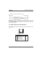
1 2 3 4 5 6 7 8
AUX1 and AUX2 connectors
(Models 65B rear panel)
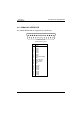
Pin Signal Name Direction
1 RTS (Request To Send) Output
2 DTR (Data Terminal Ready) Output
3 RD (Received Data) Input
4 SG (Signal Ground) ---
5 CTS (Clear to Send) Input
6 TD (Transmitted Data) Output
7 --- ---
8 DCD (Data Carrier Detected) Input
A
X3000 Models 65B