Operating manual Rel 1.
genius ENGLISH CONTENTS 1 2 3 4 5 6 7 8 9 10 11 INTRODUCTION .............................................................................................................3 OPERATIVE PRINCIPLES ..............................................................................................3 DECRIPTION...................................................................................................................6 3.1 FRONTAL PANEL........................................................................
genius ENGLISH 1 INTRODUCTION • genius is a multifunction switcher with several applications: its different configurations depend form the way the jumpers inside the equipment are set. genius can be used in the following ways: - manual or remote switcher audio detector with automatic switching balancing equipment with level setting audio distributor bi-channel splitting system or double MPX audio emergency system autofader system • genius immediateness makes its use simple allowing remote control too.
genius ENGLISH The B input features a ±10 dB amplifying section set through the potentiometer on the front panel, too. The frontal panel selector can select 3 operative modes with the following features: • AUTO: it allows remote control and the Auto Detector system can directly switch on B channel if audio is missing on A channel. If external controls are missing the A inputs are directed to the output.
genius ENGLISH pag.
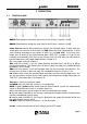
genius ENGLISH 3 DECRIPTION 3.1 FRONTAL PANEL À GAIN A: Potentiometer setting the signal level on the A input, it controls ±10 dB. Á GAIN B: Potentiometer setting the signal level on the B input, it controls ±10 dB. Â Audio detector: device able to detect the white in the selected signal; it spots when the sound does not reach the set threshold (see THR). When the white is detected the 1/16 led starts blinking according to the number of times set (see Led 1/16).
genius Å Led A R: it shows the presence of right A input in the right OUT output. Æ Led B L: it shows the presence of left B input in the left OUT output. Ç Led B R: it shows the presence of right B input in the right OUT output. 3.2 ENGLISH BACK PANEL À ON/OFF switch: it switches on the equipment, the led inside shows the status of the equipment.
genius ENGLISH Æ B IN: Left and Right inputs on connectors 3 pole XLR female connectors electronically balanced, PIN OUT standard configuration. Ç OUT DRAW: PIN RCA unbalanced output, it supplies the same signal present in B IN ; we suggest to use it as service output. È A IN: Left and Right inputs on connectors 3 pole XLR female connectors electronically balanced, PIN OUT standard configuration.
genius ENGLISH (N.B. J5∩J6 shows that you must insert the jumper between a contact in the J5 position and a contact in the J6; J5+J6 shows that you need to insert 2 jumpers, one in J5 and another one in J6). 4.2 EXTERNAL CONTROLS It is possible to connect external controls, to the Remote Interface, to remote A into B input switching and mix A and B on the outputs (MIX control). Even if the controls are connected, in order for them to work, genius should be in AUTO mode (see switcher on front panel).
genius 4.4 J1 J2 J3 J4 J21 J22 J23 4.5 J33 J34 J35 J36 ENGLISH AUDIO DETECTOR It sends the signal the Left channel of the A input to the Audio Detector adder . It sends the signal of the Right channel of the A input to the Audio Detector adder. It sends the signal of the Left channel of the B input to the Audio Detector adder. It sends the signal of the Right channel of the B input to the Audio Detector adder.
genius ENGLISH NOTE! Apart from closing Jumpers J10 e J12, to enable the 19 KHz tone when Input B is selected You need to establish again the R52 resistor which is located near IC 9 and behind the INPUT B – RIGHT XLR connector on the rear board. 4.8 J13 J14 OUTPUT LEVEL It enlarges by +6 dB the level of the Right channel output. It enlarges by +6 dB the level of the Left channel output. 4.9 J30 J31 J32 PLUG AUTOFADER (OPTIONAL) master/slave A right master slave A left stereo coupling 4.
genius J7∩J8 J9 J11 J10 J12 J13 J14 J15∩J16 J15+J16 J15 J17 J18 J19 J20 J21 J22 J23 J23+J24 J25 J26 J27 J28 J29 J30 J31 J32 J33 J34 J35 J36 P1 P2 P3 P4 P7 P12 ENGLISH A input Left channel INDEPENDENT It inserts the pre-emphasis in the signal of the Right channel in the B input. It inserts the pre-emphasis in the signal of the Left channel in the B input. It overlaps the 19 KHz to the –20dB to the signal of the Right channel of the B input.
genius ENGLISH 5 REMOTE INTERFACE Interface to connect the commands for the remote control of some functions of the genius and to control equipment connected to it.
genius Pin 8 Pin 9 ENGLISH Manual error MIX 7 INSTALLATION AND CONNECTIONS • • • • • • • • • genius has been conceived according to the present security legislation. Before starting Yr genius please check that any connection is correct and there are no wire problems. Make sure that the line voltage feeding the system corresponds to that indicated in the techìnical specifications (chapter 9). ATTENTION: genius is set at 220/230VAC, if it is fed by a different voltage (ex.
genius 7.1 ENGLISH INPUTS genius features 2 balanced XLR female inputs active with 10KΩ input impedance, and 2 DRAW outputs on PIN RCA to withdraw the A and B input signals. The A input features a ±10 dB amplification section set using the potentiometer placed on the front panel. The B input structure is different: it features a 50 μsec pre-emphasis and a 19 KHz sinusoid oscillator, both set trough jumper.
genius 7.2 ENGLISH OUTPUTS genius features an XLR male balanced output active with 100Ω impedance and a DRAW output on PIN RCA for general purposes. The output features a +6 dB amplifying section controlled by jumper. We always recommend, when possible, to realise balanced connections with good quality wires. pag.
genius ENGLISH 8 APPLICATIONS genius is a very flexible equipment and has many different application possibilities, according to its different settings. 8.1 BI-CHANNEL SWITCHER Its use as bi-channel or double mono switcher equipment does not require any internal setting. 8.2 EMERGENCY SWITCHER Its use as emergency switcher requires the enabling of the following functions and connections: 1. Connect the source to be monitored to the A input. 2. Connect the emergency source to the B channel. 3.
genius ENGLISH 9 TECHNICAL SPECIFICATIONS Input Max level : Bal. input common-mode rejection : Output Max level : Bal. output common-mode rejection : Linearity : Noise : Mains voltage: Consumption: Working Temperature: Dimension Rackmounting: Weight: +20dB 45dB 1KHz +20dB 45dB 1KHz ±0,1dB 0÷100KHz -90dB 110/220 Vac, 50/60Hz 10VA -10÷50 °C 482 x 215 x 44 mm ( 19’’ 1U ) 3,5 Kg 10 WARRANTY The warranty covered by AXEL TECHNOLOGY S.R.L. has 1 year validity ex-work.
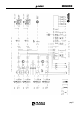
genius ENGLISH 11 TECHNICAL DOCUMENTATION • Mother Board pag.
genius ENGLISH pag.
genius • ENGLISH Front Panel pag.