
User Manual


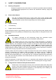

Table Of Contents
- 1. INTRODUCTION
- 1.1 Scope and Purpose of document
- 1.2 Limitation of Liability Notice
- 2. SAFETY CONSIDERATIONS
- 3. MASTER SITE RACKS (50-078001)
- 3.1 Master Site Description
- 3.P Master Site Rack Photos
- 3.2 Master Site Electrical Specification
- 3.3 Master Site Mechanical Specifications
- 3.4 Master Site Parts List (50-078001)
- 3.5 Channel Frequency Listing
- 3.6 Master Site Drawings
- 3.7 800MHz Air I/F + BSCE Uplink Shelf (50-078002)
- 3.8 800MHz 8Ch. Channel Module Sub-Rack (50-078003)
- 3.9 800MHz 40Watt Power Amplifier/Driver Shelf (50-078004)
- 3.10 VHF Simplex Shelf (50-078010/1)
- 3.11 VHF Simplex Shelf (50-078010/2)
- 3.12 VHF Duplex Shelves (50-078011/1-4)
- 3.13 VHF Air Interface Shelf (50-078012)
- 3.14 VHF Combiner Shelf (50-078013)
- 3.15 VHF PSU Shelf (50-078014)
- 3.16 VHF/800MHz Tx Multi-coupler (50-078015)
- 4. BAND SELECTIVE BI-DIRECTIONAL LINE AMPLIFIER
- 5. MASTER SITE UPGRADE
- 5.1 Master Site Upgrade Rack Assembly (50-078021)
- 5.1.1 Master Site Upgrade Rack Description
- 5.1.2 Master Site Upgrade Rack Electrical Specification
- 5.1.3 Master Site Upgrade Rack Mechanical Specification
- 5.1.6 Master Site Upgrade Rack Assembly (50-078021) Parts List
- 5.1.6a Upgrade Channel Module Shelf/Sub-Rack 50-078023 Parts List
- 5.1.7 Master Site Upgrade System Diagram, Drg. # 50-078081
- 5.2 Upgrade Channel Frequencies
- 5.3 Master Site HPA Interface Shelf (50-078005)
- 5.4 High Power Amplifier Shelf (50-146703)
- 5.1 Master Site Upgrade Rack Assembly (50-078021)
- 6. INSTALLATION
- 7. MAINTENANCE
- APPENDIX A
- APPENDIX B Initial Equipment Set-up Calculations
- APPENDIX C - BATTERY BACKUP
- C.1 GENERAL DESCRIPTION
- C.2. BATTERY BACKUP PHOTOGRAPHS
- C.3. SPECIFICATION
- C.4. GENERAL DRAWINGS
- C.5. BBU ALARMS & MONITORING SYSTEM
- C.6. INSTALLATION
- _
- C.7. MAINTENANCE

Mission Valley Radio Repeater Equipment + Upgrade
User/Maintenance Handbook
Handbook No. 50-078021HBKM Page 3 of 85
3.13.4 VHF Air Interface Shelf System Diagram, Drg. # 50-078092 ..........................................................40
3.14 VHF Combiner Shelf (50-078013) ..................................................................................... 41
3.14.P VHF Combiner Photographs............................................................................................................41
3.14.1 Description .......................................................................................................................................42
3.14.2 Technical Specification ....................................................................................................................42
3.14.3 Parts List ..........................................................................................................................................42
3.14.4 VHF Combiner Shelf System Diagram, Drg. # 50-078093..............................................................43
3.15 VHF PSU Shelf (50-078014)............................................................................................... 44
3.15.P VHF PSU Photographs....................................................................................................................44
3.15.1 Description .......................................................................................................................................45
3.15.2 Technical Specification ....................................................................................................................45
3.15.3 Parts List ..........................................................................................................................................45
3.16 VHF/800MHz Tx Multi-coupler (50-078015)...................................................................... 46
3.16.1 Description .......................................................................................................................................46
3.16.2 Technical Specification ....................................................................................................................46
3.16.3 Parts List ..........................................................................................................................................46
3.16.4 Tx Multi-coupler System Diagram, Drg. # 50-078095 .....................................................................47
4. BAND SELECTIVE BI-DIRECTIONAL LINE AMPLIFIER ...........................................48
4.1 BDA Wall Assembly (50-078017) ......................................................................................... 48
4.1.P BDA Assembly Photograph .............................................................................................................48
4.1.1 Description .......................................................................................................................................49
4.1.2 Electrical Specification .....................................................................................................................49
4.1.3 Mechanical Specification .................................................................................................................50
4.1.4 800MHz In-Line BDA System Diagram, Drg. # 50-078097 .............................................................51
4.1.5 BDA Case Outline Drawing, Drg. N. 55-118691............................................................................52
4.1.6 BDA Assembly (50-078017) Parts List ............................................................................................53
5. MASTER SITE UPGRADE........................................................................................... 54
5.1 Master Site Upgrade Rack Assembly (50-078021) ............................................................. 54
5.1.1 Master Site Upgrade Rack Description ...........................................................................................54
5.1.2 Master Site Upgrade Rack Electrical Specification .........................................................................54
5.1.3 Master Site Upgrade Rack Mechanical Specification......................................................................54
5.1.6 Master Site Upgrade Rack Assembly (50-078021) Parts List .........................................................55
5.1.6a Upgrade Channel Module Shelf/Sub-Rack 50-078023 Parts List ...................................................55
5.1.7 Master Site Upgrade System Diagram, Drg. # 50-078081..............................................................56
5.2 Upgrade Channel Frequencies ............................................................................................ 57
5.3 Master Site HPA Interface Shelf (50-078005)...................................................................... 58
5.3.P HPA Interface Shelf Photographs....................................................................................................58
5.3.1 Description .......................................................................................................................................59
5.3.2 Technical Specification ....................................................................................................................59
5.3.3 Parts List ..........................................................................................................................................59
5.3.4 HPA Interface Shelf System Diagram, Drg. # 50-078085 ...............................................................60
5.4 High Power Amplifier Shelf (50-146703) ............................................................................. 61
5.4.P High Power Amplifier Shelf Photographs ........................................................................................61
5.4.1 Description .......................................................................................................................................62
5.4.2 Electrical Specifications ...................................................................................................................62
5.4.3 Parts List ..........................................................................................................................................63
6. INSTALLATION............................................................................................................64
6.1 General Remarks .................................................................................................................. 64
6.2 RF Connections .................................................................................................................... 64
6.3 Commissioning ..................................................................................................................... 64
7. MAINTENANCE ...........................................................................................................65
7.1 Fault Finding ......................................................................................................................... 65
7.1.1 Quick Fault Checklist .......................................................................................................................65
7.1.2 Fault Isolation...................................................................................................................................65
7.1.3 Downlink ..........................................................................................................................................66
7.1.4 Uplink ...............................................................................................................................................66
7.1.5 Checking service..............................................................................................................................66
7.1.6 Fault repair.......................................................................................................................................67
7.1.7 Service Support ...............................................................................................................................67
7.2 Tools & Test Equipment....................................................................................................... 67
7.3.1 General Comments..........................................................................................................................68