VHF Headstation Bi-Directional and In-line Amplifiers User Handbook For Motorola Alaska AFL Works Order Nō.: Q112856 AFL product part Nō.: 50-127201 (Bi-Directional Amplifier) 50-127202 (In-Line Amplifier) VHF Headstation & In-Line Amplifiers User Handbook Handbook Nō.
Table of Contents AMENDMENT LIST RECORD SHEET ...................................................................................................4 INTRODUCTION.........................................................................................................................................5 Scope ........................................................................................................................................................................... 5 Purpose ..........................
4.9.1 Description ............................................................................................................................................... 32 4.9.2 Drg. Nō. 17-006880, Controller/Monitor PCB Pin-Outs......................................................................... 33 4.10 24V Single Relay Board (80-008902) ........................................................................................................ 34 4.10.1 Description ..............................................
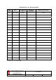
AMENDMENT LIST RECORD SHEET Issue Nō. Date Incorporated by A 14/06/2005 CMH Page No.’s Amended Reason for new issue 1st Draft Document Ref:-50-127201HBK VHF Headstation & In-Line Amplifiers User Handbook Handbook Nō.
INTRODUCTION Scope This handbook is for use solely with the equipment identified by the AFL Part Number shown on the front cover. It is not to be used with any other equipment unless specifically authorised by Aerial Facilities Limited. Purpose The purpose of this handbook is to provide the user/maintainer with sufficient information to service and repair the equipment to the level agreed.
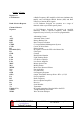
Glossary of Terms Repeater or Cell Enhancer Band Selective Repeater Channel Selective Repeater AC AGC BBU BTS CEMS C/NR DC Downlink (D/L) FO GND ID LED LNA LPA MOU M.S. MTBF N/A N/C OFR OIP3 PA RF RSA Rx S/N Tx Uplink (U/L) VSWR WDM A Radio Frequency (RF) amplifier which can simultaneously amplify and re-broadcast Mobile Station (MS) and Base Transceiver Station (BTS) signals. A Cell Enhancer designed for operation on a range of channels within a specified frequency band.
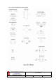
Key to AFL RF Module Drawing Symbols VHF Headstation & In-Line Amplifiers User Handbook Handbook Nō.
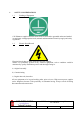
1. SAFETY CONSIDERATIONS 1.1 Earthing of Equipment Cell Enhancers supplied from the mains must be connected to grounded outlets and earthed in conformity with appropriate local, national and international electricity supply and safety regulations. 1.2 Electric Shock Hazard Electrical shocks due to faulty mains driven power supplies.
1.3 RF Radiation Hazard RF radiation, (especially at UHF frequencies) arising from transmitter outputs connected to AFL’s equipment, must be considered a safety hazard. This condition might only occur in the event of cable disconnection, or because a ‘spare’ output has been left unterminated. Either of these conditions would impair the system’s efficiency. No investigation should be carried out until all RF power sources have been removed.
1.4 Chemical Hazard Beryllium Oxide, also known as Beryllium Monoxide, or Thermalox™, is sometimes used in devices within equipment produced by Aerial Facilities Ltd. Beryllium oxide dust can be toxic if inhaled, leading to chronic respiratory problems. It is harmless if ingested or by contact. Products that contain beryllium are load terminations (dummy loads) and some power amplifiers. These products can be identified by a yellow and black “skull and crossbones” danger symbol (shown above).
2. OVERVIEW/SYSTEM DESCRIPTION The Headstation BDA and the In-Line amplifier equipment is designed to be air interfaced towards the local BTS and provide a single output to an LCX antenna cable. Automatic gain control in both paths (channel selective module in downlink path has internal AGC) keeps the signal level from overloading the amplifiers should a mobile be operated close to the LCX antenna.
3. VHF AMPLIFIERS 3.1 VHF Headstation Bi-Directional Amplifier 3.1.1 VHF Headstation Bi-Directional Amplifier Description See section 2. 3.1.
3.1.
Handbook Nō.-50-127201FCC 11-006002 Issue No:-A dB 10-000703 10-001201 dB 17-011402 137-143MHz dB 154-156MHz 01-002603 dB 137-143MHz 11-006002 01-002603 12-002001 17-001201 10-001201 10-000703 dB 155MHz(1.5MHz) 11-006002 11-006002 11-006002 12-002001 01-002603 17-001101 137-143MHz 01-002603 154-156MHz 01-002603 3.1.
3.1.5 VHF Headstation Bi-Directional Amplifier Parts List AFL Part Nō.
96-700034 96-700035 96-800003 96-900017 96-920011 96-920012 97-300010 97-300028 97-900004 LED RED 5mm IP67 LED GREEN 5mm IP67 MT2834ZDXK 56kBPS MODEM WORLD AC TRIP SWITCH (3 AMP M.C.B.) PROXIMITY SWITCH PROXIMITY SWITCH MAGNET C/E SUPPLY INPUT COVER DC BOX 24V ATO TYPE 2 ASSEMBLY RUBBER FOOT FOR CELL ENHANCERS 1 1 1 1 1 1 2 1 4 VHF Headstation & In-Line Amplifiers User Handbook Handbook Nō.
3.2 VHF In-Line Amplifier Description The In-line amplifier is almost identical to the Headstation BDA except it has lower gain. 3.2.
3.2.
Handbook Nō.-50-127201FCC Issue No:-A 17-001101 137-143MHz 01-002503 dB 12-002001 dB dB dB 12-002001 154-156MHz 01-002503 dB 137-143MHz 11-006002 01-002503 17-001101 17-001201 10-001201 10-000703 dB 10-000703 10-001201 17-001201 154-156MHz 01-002503 3.2.
3.2.4 VHF In-Line Amplifier Parts List AFL Part Nō.
96-920011 96-920012 97-300010 97-300028 97-900004 PROXIMITY SWITCH PROXIMITY SWITCH MAGNET C/E SUPPLY INPUT COVER DC BOX 24V ATO TYPE 2 ASSEMBLY RUBBER FOOT FOR CELL ENHANCERS 1 1 2 1 4 VHF Headstation & In-Line Amplifiers User Handbook Handbook Nō.
4. SUB-UNIT MODULES 4.1 4.1.1 Bandpass Filter (01-002503) Description The bandpass filters are multi-section designs with a bandwidth dependent upon the passband frequencies, (both tuned to customer requirements). The response shape is basically Chebyshev with a passband design ripple of 0.1dB. The filters are of helical design, and are carefully aligned during manufacture in order to optimise the insertion loss, VSWR and intermodulation characteristics of the unit.
4.2 4.2.1 VHF 30dB Coupler (07-000108) Description The purpose of these couplers is to ‘tap off’ known portions (usually 15-30dB) of RF signal from transmission lines, either resistively or by induction, and to combine them, for example through splitter units for different purposes (alarms/monitoring etc.), whilst maintaining an accurate 50Ω load to all ports/interfaces throughout the specified frequency range.
4.3 4.3.1 ¼Watt 0- -30dB Switched Attenuator (10-000701) Switched Attenuators The AFL switched attenuators are available in two different types; 0 – 30dB in 2 dB steps (as in this case), or 0 – 15dB in 1 dB steps. The attenuation is simply set using the four miniature toggle switches on the top of each unit. Each switch is clearly marked with the attenuation it provides, and the total attenuation in line is the sum of the values switched in.
4.4 4.4.1 VHF/UHF Low Noise Amplifier (11-006002) Description The 21dB gain low noise amplifier used is a double stage solid-state low-noise amplifier. Class A circuitry is used throughout the unit to ensure excellent linearity over a very wide dynamic range. The two active devices are very moderately rated to provide a long, troublefree working life. There are no adjustments on this amplifier, and in the unlikely event of failure then the entire amplifier should be replaced.
4.5 4.5.1 10Watt Power Amplifier (12-002001) Description The power amplifier fitted to this unit is a multi-stage, solid state power amplifier. Class A circuitry is employed throughout the device to ensure excellent linearity over a wide dynamic frequency range. All the semi-conductor devices are very conservatively rated to ensure low device junction temperatures and a long, trouble free working lifetime. The power amplifier should require no maintenance over its operating life.
4.6 4.6.1 3 Stage Amplifier Alarm Board (12-002201) Description Amplifier Alarm Boards are fitted to monitor the bias conditions of AFL Class A amplifiers which remain constant in normal operation. Any departure from normal bias conditions is a result of device failure, excess temperature, over-driving or oscillation (excessive power). In normal operation, the Class A bias circuit of the amplifier develops a constant voltage of 1.20V across the collector current setting resistor.
4.6.2 Technical Specification PARAMETER SPECIFICATION Operating voltage: 8 to 30V (floating earth) Alarm Threshold: Vcc - 1.20 volt +15% Alarm output relay contacts: Max. switch current: 1.0Amp Max. switch volts: 120Vdc/60VA Max. switch power: 24W/60VA Min. switch load: 10.0µA/10.0mV Relay isolation: 1.5kV Mechanical life: >2x10⁷ operations Relay approval: BT type 56 Connector details: 15-way 0.
4.7 4.7.1 Single DC/DC Converter (13-001710) Description This unit it is used to derive a fixed voltage power supply rail from some higher voltage. Typically, it is used to derive 5V, 8V, 12V or 15V from a 24V input. The circuit is based upon an LM317 variable voltage regulator, which is capable of supplying a maximum of 1.5A output current. Note that at full output current the dissipation of the device must remain in limits, bearing in mind the voltage which is being dropped across it.
4.8 4.8.1 Automatic Gain Control (17-001101, det. & 17-001201, atten.) Description The equipment is fitted with an Automatic Gain Control (AGC) system. This is generally fitted in the Uplink path (not usually needed in the downlink path, as the signal here is at an almost constant level), to avoid overloading the amplifiers (with the associated performance degradation) should a mobile be operated very close to the unit.
4.8.2 Technical Specification PARAMETER Frequency range: Attenuation range: Attenuation steps: VSWR: RF Connectors: Power Attenuator: Handling: Detector/amp: Temperature operation: Range: storage: Attenuator pcb: Size: Detector/amp pcb Attenuator: Weight: Detector/amp: SPECIFICATION up to 1000MHz 3 to 30dB continuously variable better than 1.
4.9 4.9.1 Controller/Monitor Board (17-006801) Description To meet the need for detailed control and status reporting of cell enhancers and other systems installed in inaccessible locations, AFL has developed an optional RS232C (RS232D) serial interface which may be incorporated into any of AFL’s range of cell enhancers.
4.9.2 Drg. Nō. 17-006880, Controller/Monitor PCB Pin-Outs VHF Headstation & In-Line Amplifiers User Handbook Handbook Nō.
4.10 24V Single Relay Board (80-008902) 4.10.1 Description The General Purpose Relay Board allows the inversion of signals and the isolation of circuits. It is equipped with a single dual pole change-over relay RL1, with completely isolated wiring, accessed via a 15 way in-line connector. The relay is provided with polarity protection diodes and diodes for suppressing the transients caused by "flywheel effect" which can destroy switching transistors or induce spikes on neighbouring circuits.
4.12 STPS12045TV 60A Dual Diode Assembly 4.12.1 Description The purpose of these dual diode assemblies is to allow two (or more) DC voltage sources to be combined, so that the main 24 volt DC rail within the equipment is sourced from either the mains driven flat-pack, or externally through an XLR connector on the rear panel. The heavy-duty diodes prevent any reverse current from flowing back to their source or the alternative supply rail.
5. INSTALLATION & COMMISSIONING 5.1 Initial Installation Record When this equipment is initially commissioned, please use the equipment set-up record sheet in Appendix A. This will help both the installation personnel and AFL should these figures be needed for future reference or diagnosis. 5.
5.3 A). Antenna Isolation First set up the two antennas & measure the isolation between them. Yagi Yagi or leaky feeder Measure Isolation Between antennas Mobiles Base Site B) Install the Cell Enhancer with its gain set 10dB below the isolation figure obtained above. Yagi Yagi or leaky feeder Base Port Mobile Port Cell Enhancer Base Site (donor) Mobile VHF Headstation & In-Line Amplifiers User Handbook Handbook Nō.
5.4 General Remarks The size and weight of the wall-mount case is such that 2/3 persons may be needed to lift the equipment into position. Test the mechanical installation in the interests of safety, before any electrical, RF, or optical connections are made. The equipment must be located on a smooth, flat, perpendicular surface, sheltered if possible, that is made from a material suitable for bearing the weight of the enclosure, (brick or concrete is recommended).
5.7 RS232 Setup The RS232 controller/monitor should not need setting up as the specified configuration with suitable firmware for the application will have been fully tested with the whole of the system before it leaves the factory. The RS232 PCB’s functions are transparent to the system if the RS232 board is powered but not utilised. Further information on the controller board’s setup and remote capabilities is available in the RS232 Controller/Monitor Handbook, AFL Nō. 17-005801HBKM.
6. MAINTENANCE 6.1 6.1.1 General Procedures Quick Fault Checklist All AFL equipment is individually tested to specification prior to despatch. Failure of this type of equipment is not common. Experience has shown that a large number of fault conditions relating to new equipment have simple causes often occurring as a result of transportation, unpacking and installation. Below are listed some common problems which have resulted in poor performance or an indicated non-functioning of the equipment.
6.1.3 Downlink Confirm that there is a signal at the expected frequency and strength from the base station. If this is not present then the fault may lay outside the system. To confirm this, inject a downlink frequency signal from a known source at the master site BTS input and check for output at the remote site feeder output. If a signal is not received at the output it will be necessary to follow the downlink path through the system to find a point at which the signal is lost.
6.1.6 Checking service Following the repair of any part of the system it is recommended that a full end-to-end test is carried out in accordance with the test specification and that the coverage is checked by survey. It is important to bear in mind that the system includes a radiating cable network and base stations that may be faulty or may have been damaged. 6.1.7 Service Support Advice and assistance with maintaining and servicing this system are available by contacting Aerial Facilities Ltd. 6.
6.3 6.3.1 Care of Modules General Comments Many of the active modules contain semiconductor devices utilising MOS technology, which can be damaged by electrostatic discharge. Correct handling of such modules is mandatory to ensure their long-term reliability. To prevent damage to a module, it must be withdrawn/inserted with care. The module may have connectors on its underside, which might not be visible to the service operative. 6.3.
5) If the amplifier to be removed has a heatsink attached, there may be several different ways it can have been assembled. The most commonly used method, is screws through the fins of the heatsink to threaded screw holes (or nuts and bolts), into the amplifier within the main case (side & top mounting).
APPENDIX A INITIAL EQUIPMENT SET-UP CALCULATIONS GENERAL INFORMATION Client Name: AFL Equip. Model Nō. Site Name: Date: Model ANTENNA SYSTEMS Gain Azimuth Comments Type Loss Comments A - Service Antenna B – Donor Antenna Length C – Service Feeder D – Donor Feeder INITIAL PARAMETERS E – CE Output Power F – Antenna Isolation G – Input signal level from donor BTS Operating Voltage dBm dB dBm V DOWNLINK CALCULATIONS Parameter Comments Input signal level (G) CE max.