
User's Manual

VHF Headstation & In-Line Amplifiers
User Handbook
Handbook Nō.-50-127201FCC Issue No:-A
Date:-14/06/2005
Page:-
2 of 45
Table of Contents
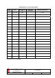
AMENDMENT LIST RECORD SHEET ...................................................................................................4
INTRODUCTION.........................................................................................................................................5
Scope ........................................................................................................................................................................... 5
Purpose ....................................................................................................................................................................... 5
Glossary of Terms...................................................................................................................................................... 6
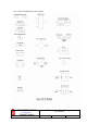
Key to AFL RF Module Drawing Symbols ............................................................................................................. 7
1. SAFETY CONSIDERATIONS.........................................................................................................8
1.1 Earthing of Equipment ................................................................................................................................ 8
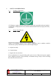
1.2 Electric Shock Hazard.................................................................................................................................. 8
1.3 RF Radiation Hazard ................................................................................................................................... 9
1.4 Chemical Hazard ........................................................................................................................................ 10
1.5 Emergency Contact Numbers.................................................................................................................... 10
2. OVERVIEW/SYSTEM DESCRIPTION .......................................................................................11
3. VHF AMPLIFIERS .........................................................................................................................12
3.1 VHF Headstation Bi-Directional Amplifier ............................................................................................. 12
3.1.1 VHF Headstation Bi-Directional Amplifier Description.......................................................................... 12
3.1.2 VHF Headstation Bi-Directional Amplifier Electrical Specifications...................................................... 12
3.1.3 VHF Headstation Bi-Directional Amplifier Mechanical Specifications................................................... 13
3.1.4 VHF Headstation Bi-Directional Amplifier System Diagram .................................................................. 14
3.1.5 VHF Headstation Bi-Directional Amplifier Parts List .............................................................................15
3.2 VHF In-Line Amplifier Description.......................................................................................................... 17
3.2.1 VHF In-Line Amplifier Electrical Specifications...................................................................................... 17
3.2.2 VHF In-Line Amplifier Mechanical Specifications................................................................................... 18
3.2.3 VHF In-Line Amplifier System Diagram .................................................................................................. 19
3.2.4 VHF In-Line Amplifier Parts List ............................................................................................................. 20
4. SUB-UNIT MODULES....................................................................................................................22
4.1 Bandpass Filter (01-002503) ...................................................................................................................... 22
4.1.1 Description ............................................................................................................................................... 22
4.1.2 Technical Specification............................................................................................................................. 22
4.2 VHF 30dB Coupler (07-000108)................................................................................................................ 23
4.2.1 Description ............................................................................................................................................... 23
4.2.2 Technical Specification............................................................................................................................. 23
4.3 ¼Watt 0- -30dB Switched Attenuator (10-000701)..................................................................................24
4.3.1 Switched Attenuators ................................................................................................................................ 24
4.3.2 Remote Attenuators (10-001201).............................................................................................................. 24
4.4 VHF/UHF Low Noise Amplifier (11-006002)........................................................................................... 25
4.4.1 Description ............................................................................................................................................... 25
4.4.2 Technical Specification............................................................................................................................. 25
4.4.3 LNA ‘D’ Connector Pin-out details.......................................................................................................... 25
4.5 10Watt Power Amplifier (12-002001) ....................................................................................................... 26
4.5.1 Description ............................................................................................................................................... 26
4.5.2 Technical Specification............................................................................................................................. 26
4.6 3 Stage Amplifier Alarm Board (12-002201)............................................................................................ 27
4.6.1 Description ............................................................................................................................................... 27
4.6.2 Technical Specification............................................................................................................................. 28
4.7 Single DC/DC Converter (13-001710)....................................................................................................... 29
4.7.2 Technical Specification............................................................................................................................. 29
4.8 Automatic Gain Control (17-001101, det. & 17-001201, atten.)............................................................. 30
4.8.1 Description ............................................................................................................................................... 30
4.8.2 Technical Specification............................................................................................................................. 31
4.9 Controller/Monitor Board (17-006801) .................................................................................................... 32