
User's Manual


800MHz Tetra Repeater
User
Handbook
Handbook Nō.-55-151501HBK Issue No:-A
Date:-22/04/2005
Page:-
2 of 31
Table of Contents
AMENDMENT
LIST
RECORD
SHEET ...................................................................................................4
INTRODUCTION.........................................................................................................................................5
Scope ........................................................................................................................................................................... 5
Purpose ....................................................................................................................................................................... 5
Glossary of Terms...................................................................................................................................................... 6
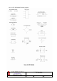
Key to AFL RF Module Drawing Symbols ............................................................................................................. 7
1.
SAFETY
CONSIDERATIONS.........................................................................................................8
1.1
Earthing of Equipment ................................................................................................................................ 8
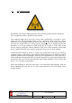
1.2
Electric Shock Hazard.................................................................................................................................. 8
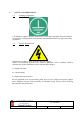
1.3
RF Radiation Hazard ................................................................................................................................... 9
1.4
Chemical Hazard ........................................................................................................................................ 10
1.5
Emergency Contact Numbers.................................................................................................................... 10
2.
SYSTEM
OVERVIEW....................................................................................................................11
3.
TETRA
BI-DIRECTIONAL
AMPLIFIER ...................................................................................12
3.P
System Photographs ................................................................................................................................... 12
3.1
Description .................................................................................................................................................. 13
3.2
Technical Specification............................................................................................................................... 13
3.3
Mechanical Specification............................................................................................................................ 14
3.4
System Drawings......................................................................................................................................... 15
3.5
Parts Lists.................................................................................................................................................... 16
4.
SUB-UNIT
MODULES....................................................................................................................17
4.1
Bandpass Filters (02-007206)..................................................................................................................... 17
4.1.1
Description ............................................................................................................................................... 17
4.1.2
Technical Specification............................................................................................................................. 17
4.2
¼Watt 0- -30dB Switched Attenuator (10-000701)..................................................................................18
4.2.1
General Application ................................................................................................................................. 18
4.2.2
Switched Attenuators ................................................................................................................................ 18
4.3
Low Noise Amplifier (11-006702).............................................................................................................. 19
4.3.1
Description ............................................................................................................................................... 19
4.3.2
Technical Specification............................................................................................................................. 19
4.3.3
LNA ‘D’ Connector Pin-out details.......................................................................................................... 19
4.4
20W Power Amplifier (12-018002)............................................................................................................ 20
4.4.1
Description ............................................................................................................................................... 20
4.4.2
Technical Specification............................................................................................................................. 20
4.4.3
PA 7-Way Connector Pin-outs.................................................................................................................. 20
4.5
5W Power Amplifier (12-018601).............................................................................................................. 21
4.5.1
Description ............................................................................................................................................... 21
4.5.2
Technical Specification............................................................................................................................. 21
4.4.3
PA 7-Way Connector Pin-outs.................................................................................................................. 21
4.6
Wide Dynamic Range AGC (17-001109, det. & 17-001201, atten.) ....................................................... 22
4.6.1
Description ............................................................................................................................................... 22
4.6.2
Technical Specification............................................................................................................................. 23
4.7
12V Single Relay Board (80-008901) ........................................................................................................ 23
4.7.1
Description ............................................................................................................................................... 23
4.8
15V Switch-Mode PSU (96-300054) .......................................................................................................... 24
4.8.1
Description ............................................................................................................................................... 24
4.8.2
Technical Specification............................................................................................................................. 24
5.
INSTALLATION .............................................................................................................................25
5.1
Initial Installation Record.......................................................................................................................... 25
6.
MAINTENANCE .............................................................................................................................26
6.1
General Procedures .................................................................................................................................... 26