Reverse Osmosis User’s Manual Model CT-4000, CT-5000, CT-7000 CT-7000 Pictured
This Page Left Blank 2 ENGF-107 REV.
Table of Contents INTRODUCTION ......................................................................................................... 4 SAFETY ....................................................................................................................... 4 FEED WATER & OPERATION SPECIFICATIONS ..................................................... 5 REJECTION, RECOVERY, & FLOW RATES .............................................................. 5 SYSTEM REQUIREMENTS & OPERATION GUIDELINES ........
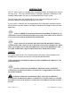
INTRODUCTION Your CT-Series system is a durable piece of equipment which, with proper care, will last for many years. This User’s Manual outlines installation, operation, maintenance, and troubleshooting details vital to the sustained performance of your system. The test results which are included with this User’s Manual indicate your system’s permeate (product) and concentrate (waste) test results.
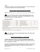
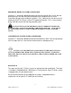
DO NOT UNDER ANY CIRCUMSTANCE; REMOVE ANY CAUTION, WARNING, OR OTHER DESCRIPTIVE LABELS FROM THE SYSTEM. FEED WATER & OPERATION SPECIFICATIONS Nothing has a greater effect on a reverse osmosis system than the feed water quality. NOTE: IT IS VERY IMPORTANT TO MEET THE MINIMUM FEED WATER REQUIREMENTS. FAILURE TO DO SO WILL CAUSE THE MEMBRANES TO FOUL AND VOID THE MANUFACTURER’S WARRANTY. OPERATING LIMITS NOTE: HIGHER TDS AND/OR LOWER TEMPERATURES WILL REDUCE THE SYSTEM’S PRODUCTION.
% Rejection = [(Feed TDS – Product TDS) / Feed TDS] x 100 Example: 98.5% = [(550-8.25)/550] x 100 NOTE: ALL TDS FIGURES MUST BE EXPRESSED IN THE SAME UNITS, TYPICALLY PARTS PER MILLION (PPM) OR MILLIGRAMS PER LITER (MG/L). CT-Series reverse osmosis systems are designed to reject up to 98.5% NaCl, unless computer projections have been provided or stated otherwise. The amount of permeate water recovered for use is expressed as a percentage.
PERMEATE (PRODUCT WATER) CONNECTION Locate the 1” connection labeled permeate and attach to storage tank. Ensure that the permeate water can flow freely with no backpressure. Backpressure can cause irreversible damage to the membrane elements. The 1” permeate line can be run to the holding tank with PVC fittings, or other FDA approved materials. This is so the material being used does not dissolve into the permeate water.
NOTE: IT’S RECOMMENDED THAT A LICENSED ELECTRICIAN WIRE YOUR SYSTEM IN ACCORDANCE WITH LOCAL AND NATIONAL ELECTRICAL CODES (NEC). WARNING: TO REDUCE THE RISK OF ELECTRICAL SHOCK, THE INCOMING POWER SUPPLY MUST INCLUDE A PROTECTIVE EARTH GROUND. CT-Series systems are typically controlled with a liquid level switch in a storage tank. The liquid level switch turns the system on when the water level in the tank drops, and off when the tank is full.
• If any damage occurs to your system’s pump a re-build kit may be available. Contact your local dealer or distributor and inform them of your system’s model and pump size. MOUNTING The free standing system should be bolted down in compliance with local regulation standards or securely fastened. MEMBRANE ELEMENTS CT-Series reverse osmosis systems come pre-loaded with Thin Film Composite (TFC) HF1 High Flow Low Energy membranes, unless otherwise specified.
HF1-STANDARD 10 ENGF-107 REV.
HF4-OPTIONAL 11 ENGF-107 REV.
HF5-OPTIONAL 12 ENGF-107 REV.
NF3-OPTIONAL 13 ENGF-107 REV.
NF4-OPTIONAL 14 ENGF-107 REV.
CT-4000, CT-5000, CT-7000 SYSTEM IDENTIFICATION FIGURE 1A 15 ENGF-107 REV.
NUMBER IDENTIFICATION 1. Solenoid Valve – Turns On/Off Feed Water 2. 5 Micron Sediment – Removes particulates 3. 10 Micron Carbon Block - Removes Chlorine 4. 1 Micron Sediment – Removes particulates 5. Pressure Gauge - Measures feed pressure 6. Pressure Gauge - Measures pressure after filters 7. Pressure Gauge - Measures pump pressure 8. Pressure Gauge – Measures concentrate pressure 9. Computer Control - Controls RO system 10. Recycle Valve – Recycles concentrate back to feed (If Applicable) 11.
FIGURE 1B FIGURE 1C 17 ENGF-107 REV.
FIGURE 1D FIGURE 1E 18 ENGF-107 REV.
FIGURE 1F Note: A portion of the frame has been removed to expose components. 19 ENGF-107 REV.
CT-4000 MEMBRANE FLOW DIAGRAM FIGURE 1G Note: Black arrows represent concentrate water and white arrows represent permeate water. 20 ENGF-107 REV.
CT-5000 MEMBRANE FLOW DIAGRAM FIGURE 1H Note: Black arrows represent concentrate water and white arrows represent permeate water. 21 ENGF-107 REV.
CT-7000 MEMBRANE FLOW DIAGRAM FIGURE 1I Note: Black arrows represent concentrate water and white arrows represent permeate water. 22 ENGF-107 REV.
SYSTEM PURGING Carefully inspect your system before initial start-up. Check that all plumbing and electrical connections are not loose or have not come undone during shipment. A User’s Manual, Test Results, and Filter Housing Wrench will accompany your CT-Series reverse osmosis system. NOTE: LEAVE THE POWER TO THE SYSTEM OFF FOR THIS PROCEDURE. 1. 2. 3. 4. Redirect permeate water to the drain for this procedure. Fully open the concentrate valve #11 (Counter Clockwise).
INITIAL START-UP 1. 2. 3. 4. 5. Keep the permeate water line to drain for this procedure. Fully open the concentrate valve #11 (Counter Clockwise). (Figure 1B, Page 16) Fully close the recycle valve # 10(Clockwise)(If Applicable). (Figure 1B, Page 16) Fully open the throttle valve #13 (Counter Clockwise). (Figure 1B, Page 16) Return position of the bypass white lever inline on the solenoid valve #1. (Figure 2, Page 22) 6.
DESIGN BASIS FOR CT-4000, CT-5000, CT-7000 WARNING: NEVER EXCEED THE MAXIMUM PRESSURE RATING OF YOUR SYSTEM. 25 ENGF-107 REV.
OPERATING DO’s & DON’Ts DO: • Change the cartridge filters regularly • Monitor the system and keep a daily log • Run the system, as much as possible, on a continuous basis. • Adjust the system recovery to the recommended value • Always feed the pump with filtered water. DON’T • Permit chlorine to enter or be present in the feed water. • Shut down the system for extended periods. • Close the throttle valve completely. • Operate the system with insufficient feed flow. • Operate the pump dry.
PRE-FILTER PRESSURE GAUGES These gauges measure the feed water pressure when it enters and exits the pre-filters. A pressure differential of 10 - 15 psi or more on the two pressure gauges indicates that the pre-filters require servicing. For example, if the inlet pressure is 40 psi, the filter should be changed when the outlet pressure is 30 psi or below. PERMEATE (PRODUCT) FLOW METER & CONCENTRATE (WASTE) FLOW METER These flow meters indicate the flow rates of the permeate and concentrate water.
Example: 98.5% = [(550-8.25)/550] x 100 % Rejection = (Feed TDS – Product TDS)/ (Feed TDS) x 100 ADJUSTING THE THROTTLE VALVE To decrease the pressure turn the handle clockwise. To increase the pressure turn the handle counter clockwise. (Figure 3, Page 23) FIGURE 3 28 ENGF-107 REV.
MEMBRANE REMOVAL & REPLACEMENT Replacing membranes in the pressure vessels is an easy process if you have the proper information and tools at hand. Please refer to the following instructions when removing and replacing membrane elements: WARNING: ALL PRESSURE GAUGES MUST READ ZERO BEFORE PROCEEDING. BEFORE ATTEMPTING, DISCONNECT THE POWER FROM THE SYSTEM AND BLEED ALL WATER PRESSURE FROM THE SYSTEM. 1. Remove the end caps from the top of the membrane housings.
1. Remove one membrane element at a time from the membrane element housings, from the top of the housing. Long nose pliers may be necessary to pull the old membrane element out of the membrane element housing. 2. Lubricate the brine seal with non petroleum based lubricant, Silicone DC 111. 3. Install the brine seal side of the membrane element first (Figure 4, Page 30). When the housings have a direction of flow from bottom to top, the brine seal should be located at the bottom of the housing. 4.
FIGURE 4 View from the back of CT-4000, CT-5000, and CT-7000 reverse osmosis system. 31 ENGF-107 REV.
FLUSHING THE SYSTEM The system should be flushed weekly to remove sediment from the surface of the membranes. To manually flush the system follow the preceding steps: 1. The system must be operating during the flush procedure. 2. Fully open the concentrate valve. (Figure 1B, Page 16) 3. Allow the system to run for 10 to 20 minutes. 4. After 10 to 20 minutes, close the concentrate valve to its previous setting. Ensure the proper concentrate flow rate is going to the drain. 5.
5. Disconnect the inlet, concentrate, pre-filter, and permeate plumbing. 6. Drain all water from the pre-filter cartridge housings by unscrewing the housings, removing the pre-filter cartridges, and drain the water from the housings. 7. Disconnect the tubing from the connectors on the permeate and concentrate inlets and outlets. 8. Fully open the concentrate valve. 9. Drain the flow meters. 10. Allow the system to drain for a minimum of eight hours or until the opened ports quit dripping. 11.
REVERSE OSMOSIS TROUBLESHOOTING SYMPTOMS Low Inlet Pressure Low Permeate Flow High permeate flow Poor permeate quality POSSIBLE CAUSES Low supply pressure Increase Inlet Pressure Cartridge filters plugged Change Filters Solenoid valve malfunction Replace Sol. Valve and/or Coil Motor may not be drawing correct current Use clamp-on amp meter to check the motor amp draw.
ABNORMAL PERMEATE FLOW Permeate flow should be within 20% of the rated production, after correcting the feed water temperatures above or below 77°F. Check your permeate flow meter to determine the permeate flow rate. NOTE: TO DETERMINE THE TEMPERATURE CORRECTION FACTOR, LOCATE THE TEMPERATURE CORRECTION TABLE IN THIS USER’S MANUAL AND FOLLOW THE DIRECTIONS 35 ENGF-107 REV.
TEMPERATURE CORRECTION FACTORS FOR MEMBRANE Find the temperature correction factor (TCF) from the table below. Divide the rated permeate flow at 77°F by the temperature correction factor. The result is the permeate flow at the desired temperature. (See example on the next page) 36 ENGF-107 REV.
If a system is rated to produce 5 gpm of permeate water @ 77˚ F. The same system will produce more water at a higher temperature. It will also produce less water at a lower temperature. Use the temperature correction table to obtain the correct flow. Example: 5 gpm @ 59˚ F (5÷1.42=3.52 gpm) 5 gpm @ 77˚ F (5÷1=5 gpm) 5 gpm @ 84˚ F (5÷0.89=5.62 gpm) SERVICE ASSISTANCE If service assistance is required, please complete the following process: Contact your local dealer or distributor.
OPERATION Company: ____________________ Date of StartUp: ___________________ ____________________ Date of Last Cleaning: ___________________ Location: Week Of: System Serial #: ____________________ ____________________ Date Time Hour of Operation Filter inlet pressure (psi) Filter outlet Pressure (psi) Concentrate Pressure (psi) Pump Discharge Pressure (psi) Feed Flow (gpm) Permeate Flow (gpm) Concentrate Flow (gpm) Recovery % Feed Temperature Feed TDS (ppm) Permeate TDS (ppm) Rejection % Feed PH
DRAWINGS FIGURE 5 39 ENGF-107 REV.
FIGURE 6 40 ENGF-107 REV.
FIGURE 7 41 ENGF-107 REV.
FIGURE 8 42 ENGF-107 REV.
Note: A portion of the frame has been removed to expose components. FIGURE 9 43 ENGF-107 REV.
CT-4000 SYSTEM PART LIST Item No. Qty. Part No. Description 1……………2………..200901……GAUGE, BTM, NO FILL, 0-100PSI/BAR, 2” DIA 2……………1………..204914……VALVE, SOLENOID, N/C, UL, 220V, 1” FNPT 3……………1………..200640……CART, SEDIMENT, POLYPRO, 4.5”x 20”, 5 MIC 4……………1………..200663……CARTRIDGE, CARBON, BLOCK, 4.5”x 20”, 10 MIC 5……………1………..200639……CART, SEDIMENT, POLYPRO, 4.5”x 20”, 1 MIC 6……………3………..203649……HOUSING, FILTER, BLK/BLU, 4.5”x 20”, 1” FNPT 7……………1………..
CT-5000 SYSTEM PART LIST Item No. Qty. Part No. Description 1……………2………..200901……GAUGE, BTM, NO FILL, 0-100PSI/BAR, 2” DIA 2……………1………..204914……VALVE, SOLENOID, N/C, UL, 220V, 1” FNPT 3……………1………..200640……CART, SEDIMENT, POLYPRO, 4.5”x 20”, 5 MIC 4……………1………..200663……CARTRIDGE, CARBON, BLOCK, 4.5”x 20”, 10 MIC 5……………1………..200639……CART, SEDIMENT, POLYPRO, 4.5”x 20”, 1 MIC 6……………3………..203649……HOUSING, FILTER, BLK/BLU, 4.5”x 20”, 1” FNPT 7……………1………..
CT-7000 SYSTEM PART LIST Item No. Qty. Part No. Description 1……………2………..200901……GAUGE, BTM, NO FILL, 0-100PSI/BAR, 2” DIA 2……………1………..204914……VALVE, SOLENOID, N/C, UL, 220V, 1” FNPT 3……………1………..200640……CART, SEDIMENT, POLYPRO, 4.5”x 20”, 5 MIC 4……………1………..200663……CARTRIDGE, CARBON, BLOCK, 4.5”x 20”, 10 MIC 5……………1………..200639……CART, SEDIMENT, POLYPRO, 4.5”x 20”, 1 MIC 6……………3………..203649……HOUSING, FILTER, BLK/BLU, 4.5”x 20”, 1” FNPT 7……………1………..
CT-4000 FLOW DIAGRAM 47 ENGF-107 REV.
CT-5000 FLOW DIAGRAM 48 ENGF-107 REV.
CT-7000 FLOW DIAGRAM 49 ENGF-107 REV.
110/220V 50/60 Hz 1 PHASE ELECTRICAL SCHEMATIC Minitrol 50 ENGF-107 REV.
208/220V 50/60 Hz 3 PHASE ELECTRICAL SCHEMATIC Minitrol 51 ENGF-107 REV.
110/220V 50/60 Hz 1 PHASE ELECTRICAL SCHEMATIC Minitrol IF 52 ENGF-107 REV.
208/220V 50/60 Hz 3 PHASE ELECTRICAL SCHEMATIC Minitrol IF 53 ENGF-107 REV.
ENGF-107 REV.