Fluid-O-Tech PUMP TECHNOLOGY AT ITS BEST Office: 161 Atwater St., Plantsville, CT 06479 WWW.FLUID-O-TECH.COM Phone: (860) 276-9270 Fax: (860) 620-0193 “ROTOFLOW” ROTARY VANE PUMP REBUILD MANUAL 08/09 Ed., Rev.
Contents 1) Materials Needed 2) Disassembly 3) Inspection 4) Reassembly 5) Testing 6) Rebuild Specifications CAUTION: Proper safety precautions should always be observed. Always wear proper eye protection when working. 08/09 Ed., Rev.
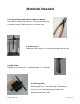
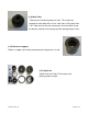
Materials Needed # 1) Internal Retaining Ring Pliers/Spanner Wrench Pliers with the capacity to remove a 2” internal retaining ring, or spanner wrench if your pump has a screw-on cap. # 2) Arbor press Arbor press with at least 12“ of clearance underneath the ram. # 3) Metal Rod Rod to press out the shaft. It should be about .4” in diameter. # 4) Bearing puller Bearing puller for 11 mm ID bearings. Alternatively, you can use a shallow tapered pin to press the bearing out from the inside. 08/09 Ed., Rev.
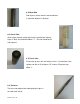
# 5) Metal Rod Rod to press out the washer and counterface. It should be about 3/4“ diameter. # 6) Plastic Rod Short length of plastic rod for pressing the counterface in place. Nylon is ideal, and should be about 1.1”. The end should be flat and squared. # 7) Plastic tube Plastic tube to press the seal onto the shaft. It should have a flat, square end with an ID of about .475” and an OD greater than about 1”. # 8) Tweezers These are not required, but make putting the pins in the rotor much easier.
# 9) Metal Tube Tube to press the bearing onto the shaft. This can be any squared off metal tube with an ID of .440” and an OD greater than m 1.25”. Note that this tube must contact the inner and outer ring of the bearing, otherwise the bearing could be damaged upon install. # 10) Blocks or supports Blocks or supports to hold the pump when pressing pieces in or out. # 11) Repair kit Repair kit for the Fluid-O-Tech rotary vane pump you plan to repair. 08/09 Ed., Rev.
Disassembly 1) If your pump has a retaining ring on the cap, use the retaining ring pliers to remove the ring. Supporting the pump under the arbor press and using the ram to apply pressure aids in removal of the retaining ring, and can help prevent it from flying off. If your pump has a sticker on the cap and no retaining ring, remove the sticker. You will see two small holes on the outer edge and one larger hole in the center.
6) Once the bearing is out, support the pump again on its rim with the bearing end facing up, making sure nothing is obstructing components from being pushed out of the body. Now use the metal rod (material #5) to press out the washer, counterface, and any remaining pieces. Be sure that the rod presses only on the washer, and not on the small retaining ring or lip. The pump body should now be empty, with only the small retaining ring and ball bearing oring left inside. These are normally reused. 08/09 Ed.
Inspection Once disassembled, the reusable components of the pump will need to be inspected for damage. This includes the body, the rotor and the bypass. 1) Pump Body: Check the pump body for dents on or around the rim that may impair the insertion of the new graphite. The rim or ports are the most likely areas for a pump to be dented, and dents can crack graphite as it is being inserted or keep fittings from screwing in the ports.
out, and/or wear the graphite quickly. First, visually inspect the rotor for surface finish, nicks, or scrapes. If it appears in good shape it should be tested. Run a new vane through each slot by hand. It should slide freely through each slot. Assemble the rotor with the vanes, pins(if applicable), liner, and flanges. The rotor should spin smoothly and easily by hand.
Reassembly 1) Before beginning to reassemble the pump, make sure all the pump parts and your work area are clean. The clearances of the pump are very tight, and even small particles can damage the pump or keep it from functioning properly. Carefully refer to the parts diagram to ensure the proper selection and orientation of all parts. 2) Start by assembling the graphite and rotor. Locate the rear flange.
9) Sometimes pushing the seal over the shaft in the next few steps can be difficult. It helps to wet the seal and shaft with water, or even better, ethyl alcohol prior to doing this. The same applies to the counterface which will be inserted later. Do not use any type of grease or oil to install the seal or counterface. This can result in the shaft slipping in the seal during use, which will rapidly wear the rubber, and cause the pump to leak.
13) Take the pump body place it over the top of the rotor/graphite assembly, with the acorn nut facing directly to the left and the ports facing upward (toward 12 o’clock). Locate the ball bearing and position it in the hole on the top of the pump body. Using the metal tube (material #10), press the body and bearing over the graphite/rotor assembly slowly and carefully, guiding the graphite into the pump as you go.
the screw back into the acorn nut, returning it to the desired setting. If you want to test the bypass setting, refer to the section “Testing” below. 08/09 Ed., Rev.
Testing It is recommended that the pump be tested before being put into service, to ensure that the pump was assembled properly and is running satisfactorily. The pump can be tested as follows: 1) Connect the pump to a motor using the proper coupling and adapter if necessary (contact Fluid-o-Tech for details, or visit www.fluidotech.com). Plumb the inlet of the pump directly to a source of clean water, using tubing with an ID sufficiently sized for the flowrate of the pump.
this the pump performs properly without leaking, it has been successfully rebuilt. If the cap leaks, the cap o-ring and mating surfaces should be checked and replaced if necessary and re-tested. If the pump leaks from the weep holes, the seal and counterface should be checked and/or re-placed, then reassembled and tested. 4) The max bypass pressure can also be adjusted at this time if desired. This only applies to those pumps equipped with an acorn nut on the inlet.
Rebuilding Specifications Liner Inside Diameters: 070 32.7mm 100 32.9mm 150 33.3mm 200 33.7mm 250 34.1mm 300 34.4mm 350 34.8mm 400 35.2mm 070 16.2mm 100 16.2 mm 150 16.5mm 200 16.9mm 250 17.2mm 300 17.6mm 350 17.9mm 400 18.1mm Pin Lengths: Max Shaft Torque: 2.6 in.-lbs. Seal Depth: 21mm +/- .1mm Ball Bearing: 11mm ID 30 mm OD 08/09 Ed., Rev.