INTRODUCTION OVERVIEW The Axesstel TX240G is a dual-band (800/1900Mhz) fixed wireless voice terminal that is perfect for a seamless land-line like service. TX240G is designed to provide a simple phone service at a home or business. Its Assisted GPS feature provides E911 service to accurately determine the location of the caller in case of an emergency. Axesstel’s TX240G allows the users to migrate from landline to wireless without losing any functionality of their regular home phone service.
TABLE OF CONTENTS INTRODUCTION.......................................2 Using # as Send Key………….…………19 Overview...................................................2 Setting DTMF Length............................19 Features....................................................2 SECURITY Safety Precautions..................................4 Changing Lock Code….........................20 Package Content………….......................5 Restricting Outgoing Calls….................20 Factory Reset…….………........
SAFETY PRECAUTIONS 1. Avoid placing the terminal in a dusty location, or near a source of gas or fire. 2. Do not shake, hit or drop the terminal. 3. To clean the outside of the terminal, use only a soft, dry cloth, as chemicals such as alcohol, benzene or acetone can damage the surface of the terminal. 4. Do not twist or pull the cables. 5. Do not disassemble the terminal. 6. Do not use the power adapter if: - The power cord is damaged. - The adapter has been damaged in any way. 7.
PACKAGE CONTENTS After opening the package, check to make sure that you have all the parts shown below. If any item is missing or broken, please call your service provider’s support center.
BASIC INSTALLATION INTERNAL BATTERY INSTALLATION This TX240G operates by receiving electricity from an electrical outlet or internal battery. 1. Open the battery cover on the bottom side of the terminal. 2. Connect the Battery power cable to the terminal. 3. Insert the battery pack in the right position between the hold bars. 4. Close the battery cover. SETTING UP THE TERMINAL 1. Connect the antenna by screwing it into the TNC connector on the back of the terminal. 2.
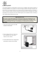
Connecting the Terminal to Home Phone Wall Outlet. The TX240 can be connected to a home wall phone jack to generate a dial tone service throughout the entire home and allow users to use phones from any other home wall phone jack. Please verify that the home wall phone jacks do not have existing active telephone service and that they are not powered. Before connecting the terminal to home wall jack, please test with the included “Wall Jack Tester”.
RJ-11 CROSS ADAPTOR (Line 1 to Line 2 Bypass Adapter) If the first line of the phone line is live and has power, you may still be able to use the terminal through your home phone wiring by using the RJ-11 cross adapter. Line 1 uses the middle two pins on the RJ11 cable. Line 2 uses the outer two pins on the RJ-11 connector. IMPORTANT NOTE Some house wirings may only have line 1. Some houses may have both line 1 and line 2 wires live.
A-GPS for E911 Your terminal supports an A-GPS feature to meet a FCC 911 mandate, which makes the location of the terminal available to 911 operators in the case of emergency situations. During the emergency call, all the LEDs on the terminal will blink and your location can then be determined by the 911 operator.
WALL MOUNT INSTALLATION 1. Mark two mounting hole locations on a wall to match the screw holes on the back of the terminal. 2. Drill two holes and put screws at the marked locations. 3. Tighten the screws until the head is about 5mm from the wall. 4. Plug in the AC power connector and route the power cord in the groove, if needed. Connect antenna. 5. Hang the terminal on the screws using the two holes on the back. 6. Push the terminal down until the unit is firmly locked into place.
GETTING TO KNOW THE TERMINAL LED INDICATORS Item Color Status Description In Battery Mode: Fully Charged Full POWER Solid In Adaptor Mode: Connected Green Blinking Charging Solid Mid Battery Level Orange Blinking Battery Error Solid Low Battery Red Blinking SIGNAL MODE/MSG Low Battery Warning Off - No Battery Green Solid Excellent Signal Orange Solid Good Signal Red Solid Low Signal OFF - No Service Solid Off-Hook or In Use Green Blinking Incoming Call Orange Blinking
AUDIBLE INDICATIORS No Tone Cadence Remark 1 Dial Tone Continuous beep 330ms ON / OFF 660ms ON / OFF Terminal is in service area and can make calls. 2 Busy Tone Beep - beep - beep 0.5s ON / 0.5s OFF Recipient line is busy 3 Howler Tone 4 No Service Tone 5 Function Confirm Tone Escalating bee – bee -beep 1046Hz: 350ms ON 1328Hz: 350ms ON 1567Hz: 350ms ON Used when accessing menu. Menu selection or configuration successful 6 Function Error Tone Three Short Beeps Used when using menu.
Basic Operation POWER ON/OFF MAKING CALLS RECEIVING CALLS 13
POWER ON / OFF The power switch is located on the back side of the terminal 1. Turn on the unit by moving switch to ON position. 2. Turn off the unit by moving switch to OFF position. NOTE: When you turn on the terminal, it automatically searches for cellular service. After successfully acquiring cellular service, the Signal LED turns to Green, Orange or Red depending on signal strength. MAKING CALLS 1. Check if the terminal is turned on. 2. Pick up the handset of the phone. 3.
RECEIVING CALLS The wired or cordless telephone(s) connected to the terminal ring when an incoming call comes in. 1. Pick up the phone receiver to answer the call. 2. To disconnect after the call is finished, place the handset on the phone hook or press the TALK or OFF button on your phone. NOTE 1: If using cordless phone, press TALK or ON button to answer the phone call. .Refer to the cordless phone user manual for instruction. NOTE 2: Make sure that the attached telephone(s) ringers are enabled.
Advanced Features SOUND ○ ○ ○ ○ ○ ADJUSTING VOICE VOLUME ADJUSTING ALERT TONE VOLUME SETTING ONE MINUTE ALERT SETTING VOICE PRIVACY ALERT SETTING CONNECTION ALERT .GENERAL ○ SETTING CALLER ID ○ CALL WAITING ID ○ CALLER NAME DISPLAY ○ SETTING AUTO SEND TIME ○ USING # AS SEND KEY ○ SETTING DTMF LENGTH .SECURITY ○ CHANGING LOCK CODE ○ RESTRICTING OUTGOING CALLS ○ FACTORY RESET .
SOUND ADJUSTING VOICE VOLUME You can control the volume level of the terminal. 1. Pick up the handset and listen to the dial-tone. * □ * □ 1□ 1□ * to raise the voice volume. 2. Press □ * □ * □ 1□ 1□ # to lower the voice volume. 3. Press □ 4. A confirmation beep will sound. NOTE 1: Some phones may have their own volume control. Use both the terminal and the phone .volume controls to optimize the sound level. NOTE 2: Volume cannot be adjusted while a conversation is in progress.
SETTING CONNECTION ALERT If enabled, a discrete tone is generated on the receiver when a call is connected. To change the setting: 1. Pick up the handset. * □ * □ 1□ 5□ # to enable the feature. 2. Press □ * □ * □ 1□ 5□ * to disable the feature. 3. Press □ NOTE: The default setting may depend on the service provider.
SETTING AUTOSEND TIME Similar to a landline phone, the terminal automatically makes the call shortly after the user finishes entering the phone number. To change the setting: 1. Pick up the handset. * □ * □ 2□ 2 Then press □ 3 ,□ 9 or □ 0 and press □ #. 2. Press □ * □ * □ 2□ 2□ 5□ #. For example, to set the auto-send time to 5 seconds, press □ NOTE 1: 0 value disables auto-send. If disabled, the user must press □ # to make a call. □ # functions as a SEND key on the mobile phone.
SECURITY CHANGING LOCK CODE The lock code prevents the terminal from being used by an unauthorized person without 0□ 0□ 0□ 0. permission. The default lock code is □ To change the lock code: 1. Pick up the handset. * □ * □ 3□ 1. 2. Press □ 0□ 0□ 0□ 0 , a short beep will sound as confirmation. If 3. Enter the old 4 digit lock code. For example □ not correct, an error tone will sound and the terminal will return to standby mode. 4. Enter the new 4 digit lock code followed by □ # .
FACTORY RESET Reset the user configuration to factory default settings. 1. Pick up the handset. * □ * □ 3□ 5. 2. Press □ 3. Enter the 4 digit lock code. If not correct, an error tone will sound and the terminal will return to standby mode. # to reset. 4. Press □ NOTE 1: The default lock code is □ 0□ 0□ 0□ 0 . To change, refer to “Changing Lock Code” section. NOTE 2: Factory reset includes auto send time, lock code, call restrictions, caller ID type, voice .
Optional Features CALL WAITING THREE-WAY CALLING VOICE MAIL SERVICE 22
CALL WAITING Call Waiting is a feature which enables you to be alerted to a second incoming call when you are already on a phone call. Your service provider may or may not provide this feature. Please contact with your service provider to inquire. To use call waiting: 1. You will hear a beep from the earpiece when a second call is incoming. 2. Press the hook or press the FLASH key to answer to the second call. 3. Press the hook again or press the FLASH key to return to the first call.
Miscellaneous MENU OPTION TABLE TROUBLESHOOTING SPECIFICATION 24
MENU OPTION TABLE Access the menu by first lifting the handset or pressing the TALK button and their pressing ** followed by the appropriate number sequence as shown below. MENU ("**○○") Sub Menu ITEM 1. Adjusting Voice Volume 2. Adjusting Alert Volume 1.Sound 3. Setting 1 Minute Alert 4. Voice Privacy Alert 5. Connection Alert 1. Setting Caller ID 2. General 2. Setting Auto Send time # as Send key 3. □ 4. Setting DTMF Length 1. Changing Lock code 3. Security 4.
TROUBLESHOOTING Problem: I Can’t Place a Call 1. Check the Terminal’s Power LED to make sure the Terminal is ON. 2. Check the antenna to make sure it is tightly connected to the Terminal. 3. Check the phone cord to make sure it is properly connected between the Terminal’s RJ-11 port and the Telephone’s RJ-11 port. 4. In case that the telephone isn’t functioning properly, try connecting the Terminal to a different telephone. 5.
SPECIFICATIONS Item Description Remark Air Interface CDMA2000 1X RF Frequency 800MHz/1900Mhz Dual band LED Indicator - 3 multi color - POWER, SIGNAL and MODE/MSG Green, Orange, Red, Off Interface - 2 RJ-11 Ports (bridged), Max 5 REN - DC power Jack - Power ON/OFF Switch - TNC Connector for CDMA antenna - SMA Connector for A-GPS antenna Battery - Li-ion rechargeable battery - Capacity :1000mAh (Standard) * Stand by time: 7Hrs * Talk time:1Hr Power Adapter - Input: AC100-240V, 50/60Hz - Output