
User`s guide


1: Introducing IP-Intercom • 2
Version 1.2 July 2010
IP-Intercom Stations: Front Panel
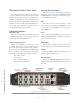
The rackmounted Livewire IP-Intercom stations in-
corporate a number of front panel connectors, controls
and indicators to allow the operator to operate the system
quickly and confidently. Front and rear panel views are
shown for the 20-station OLED display and the 10-sta-
tion film-cap user-legendable stations. The Element con-
sole versions of these stations incorporate the same con-
trols in slightly different physical layouts.
Front Panel Connectors
Microphone Jack
This jack is used for a panel-mount microphone with
a 1/4 inch Tip-Ring-Sleeve connector. One popular inter-
com microphone is the Telex MCP-90-8.
Intercom Headset Connector
This is a 4-pin XLR-M connector used to connect
an industry standard intercom headset that incorporates
both a microphone and a headphone. One example is
the Production Intercom SMH210 Single Muff Headset.
There are numerous other manufacturers of these head-
sets that all use the following 4-pin wiring convention:
Pin 1: Mic common
Pin 2: Mic hot
Pin 3: Headphone common
Pin 4: Headphone hot (mono)
Intercom Channel Controls
This section provides only some basic information
on the device controls. Please refer to Chapter 2: Setup
and Operation for an in-depth discussion of the opera-
tion of the IP-Intercom panels.
Talk
This button may be used in momentary or latch
modes. You may press and hold the Talk button to talk.
You may also tap to latch Talk mode and tap again to
release Talk mode.
Listen
Press and hold the Listen button to listen momen-
tarily. Tap the Listen button to latch Listen mode and tap
again to release Listen mode.
OLED Display
This 10-character display shows the Label of the
channel assigned to the adjacent Talk and Listen buttons.
Volume
The rotary Volume control is used to adjust the over-
all level of the loudspeaker audio.
Mute Microphone
Tapping the Mute Microphone button alternately
enables and disables the microphone ensuring privacy if
necessary.
Figure 1-1: IC.20 - Front Panel Callouts