
User`s guide

1: Introducing IP-Intercom • 3
Version 1.2 July 2010
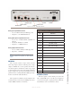
Mute Speaker
Tapping the Mute Speaker button alternately en-
ables and disables the audio from the local speaker.
Select
The Select control is used to scroll through various
menu options and to and select from pending calls. See
the section that follows on the CALLSTACK channel.
Group
The Group button enables the user to talk to multiple
users with one press.
Assign/Enter
This button is used to assign devices to the IP-Inter-
com Group. It doubles as the “enter” key. See Chapter 2
for details on Group functions.
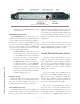
CALLSTACK Controls (20-Station Panel)
This channel is used for monitoring and calling sta-
tions that are not assigned to a specific Talk/Listen chan-
nel on the user’s panel. See Chapter 3 for details.
Keypad (20-Station Panel)
A 12-button telephone-style dialing keypad will be
used for features to be added in the future.
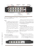
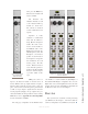
Filmcap Buttons (Programmable)
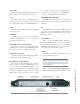
The model IC.1 rackmount 10-key Intercom station,
shown in Figure 1-2, features 10 buttons that are used
in the same manner as the Talk/Listen buttons on the
20-channel unit. These functions are programmed in the
web browser configuration. Button caps are manually
labelled using your favorite word processor or spread-
sheet software. Create the 1/2 inch square labels for
these buttons. Use your fingers to pop off the button cap
and insert your label behind the clear button cap.
Livewire Status Indicators
Four LEDs indicate the status of the Livewire and
Ethernet connections, as well as system synchronisation
as follows:
Net
When illuminated continuously, this LED represents
the presence of a live Ethernet link to another Ethernet
100Base-T device. If no Ethernet link is present, this
LED flashes slowly.
Sync and Master
Only one of these two LEDs should be illuminated.
The SYNC LED indicates the receipt of clock informa-
tion from another (Master) Livewire device. The MAS-
TER LED indicates that this device is acting as the mas-
ter clock source for the Livewire network.
Livewire
This LED indicates that Livewire traffic is present on
the connected Ethernet segment.
NOTE: Axia console mounted IP-Intercom sta-
tions use the Control Room Microphone and the
Preview speaker instead of the mic/line inputs
and front panel speaker of the rack-mount mod-
els discussed here.
Please refer to Chapter 2: Setup and Operation for
detailed descriptions of the IP-Intercom station controls.
Figure 1-2 IC.1 Front Panel Controls