
User`s guide


1: Introducing IP-Intercom • 4
Version 1.2 July 2010
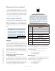
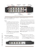
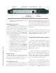
IP-Intercom Stations: Rear Panel
All rackmounted intercom stations have identi-
cal rear panel configurations with the exception of the
10-station intercom expander. This expansion unit has
only a Livewire jack, ID button and AC connector. The
rear panel of the 20-station panel is illustrated in Figure
1-4 and described in the following section.
Livewire (100 Base-T) Connector
This connector is for connection to an approved Eth-
ernet switch. It has two integral LEDs. The green “Link”
LED indicates the presence of a live signal (same as the
front panel “NET” LED). The “Activity” LED indicates
that Ethernet packets are being sent or received over the
link.
IMPORTANT NOTE: Axia IP-Intercom stations
are intended for use with an Ethernet Switch
that supports multicast and QOS (Quality of
Service). If you attempt to use them with non-
switched Ethernet hubs, or a switch that is not
enabled for multicast, you will experience net-
work congestion that could disrupt other net-
work activity. Information on qualied Ethernet
switches is found here: http://www.axiaaudio.
com/switches/default.htm
ID Button
This recessed switch allows you to assign an IP ad-
dress to a new unit. An IP address is required so you can
use your web browser to setup the advanced features of
the IP-Intercom panel. When the ID button is pressed,
you are prompted to enter an IP address and subnet mask
from the front panel controls. Pressing this button also
triggers the IP-Intercom panel to identify itself and re-
quest an IP address from a BootP server on the Ethernet
network (more on this later).
Audio Input and Output Connectors
Line Level Analog Audio
All RJ-45 line-level input and output connections to
IP-Intercom stations are dual channel connectors. Each
pair of audio inputs on the Analog Line shares an 8-posi-
tion / 8-pin RJ-45 modular jack. The connector pin func-
tions are shown in the table that follows. Inputs are mono
- left channel only. Outputs are dual channel mono.
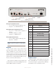
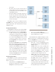
Figure 1-3: RJ-45 Pin Locations
81
IMPORTANT NOTE: Axia recommends using
balanced audio for analog audio connections.
If unbalanced sources are to be connected to
these inputs, we strongly recommend using a
balun (transformer) or balanced-to-unbalanced
buffer amplier at the source device. Such
devices are readily available, for example the
StudioHub “Match Jack”.
RJ-45 ANALOG LINE CONNECTORS
Pin Function:
1 Left Channel +
2 Left Channel -
3 Right Channel + (on output only)
4 Not Connected
5 Not Connected
6 Right Channel - (on output only)
7 Not Connected
8 Not Connected
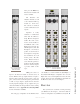
Three-pin XLR connectors are also available for
mono line level analog audio connection in and out of
the IP-Intercom rear panel. Industry standard pin con-
ventions are followed.
Pin 1: Ground (optional connection)
Pin 2: Analog Audio +
Pin 3: Analog Audio -
Microphone Input
A 3-pin XLR-F connector is supplied for a balanced
microphone input to the system. Phantom Power is en-
abled from the web page configuration.
Pin 1: Ground (Mic shield)
Pin 2: Microphone +
Pin 3: Microphone -