
User`s guide

Version 1.2 July 2010
2: Basic Setup and Operation • 10
• In all menus, selecting Back will take you back
to the Home Page.
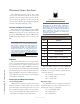
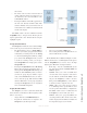
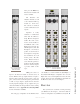
CALLSTACK (20-Station Panel)
This CALLSTACK channel (found only on the
20-station rackmount panel and the 20-station Element
console module) is used for monitoring and calling sta-
tions that are not assigned to a specific Talk/Listen chan-
nel on the user’s panel. The OLED lists up to four ring-
ing, active and last completed calls. Press Talk to talk
to the present source displayed. You can use the Select
control to scroll through the call list.
• The Listen LED flashes yellow when the local
user is being called by a station not assigned to
one of the Talk/Listen channels on the called sta-
tion panel, and continues to flash for approxi-
mately 40 seconds or until call is answered.
• The Talk LED flashes red when a remote user
is attempting to Listen to you. The Talk LED
is solid red when you have selected Talk Mode.
It may flash red to indicate a fault (attempt to
communicate with faulty or disconnected panel,
route is locked out by studio IFB, system failure
prohibits completing route, etc.)
Keypad (IC.20 only)
The keypad will be used for enhancements that will
be added in the future. In a networked studio environ-
ment, there are many possibilities. Stay tuned - we
wouldn’t put it there if we didn’t have a plan for it!
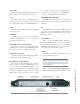
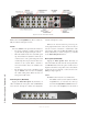
Film-Cap Buttons (IC.1 only)
The 10-button Intercom panel shown in Figure 2-4
features 10 film-cap buttons that are programmed in the
web page setup of the IC.1. These buttons may be con-
figured as Talk or Listen buttons. They may also be con-
figured as combination Talk/Listen buttons that provide
the equivalent of pressing both the Talk and Listen but-
tons on an IC.20 station. This allows an IC.1 user to open
up full two-way communication with a user by pressing
a single button.
Note that the Film-Cap buttons cannot be pro-
grammed from the front panel of the IC.1. The web
page setup must be used to configure these buttons. See
Chapter 3: Advanced Programming for details.
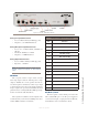
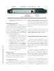
Console-Mounted Intercom Stations
Connecting console-mounted IP-Intercom stations
couldn’t be easier. Each of these modules is equipped
with a CANBus RJ-45 connector. All data communica-
tion and power is provided by the CANBus connection.
The console-mounted modules are highly integrated
with the Element console and do not have dedicated
GPIO or audio connectors.
To get started, simply connect the IP-Intercom con-
sole module to the CANBus distribution hub in your
Element console using a CAT5-E patch cable. Note
that more than one IP-Intercom module in an Element
console is unsupported so any setting of the ID selector
switch on the circuit board will be acceptable.
Once you have connected the Intercom module, it
may be necessary to ensure that the Element knows
about it. To do this, enter the Element capture mode by
pressing both * and 2 keys on the Element keypad for 5
seconds. When you see “Capture” displayed above each
Figure 2-4: IC.1 Front Panel Controls