
User`s guide
3: Advanced Programming • 16
Version 1.2 July 2010
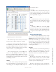
4. Default (Dim lower priority sources; Mute IFB)
5. Above Normal (Dim lower priority, Mute Low
Priority and IFB)
6. Above Normal (Dim low priority, Mute Low Pri-
ority and IFB)
7. High (Mute lower priority sources)
8. Highest (Mute lower priority sources)
Dimming and muting of external sources is config-
ured on the Ext Sources page (described in the next sec-
tion).
Dim Level
This setting specifies the degree of dimming. It is
variable from 0 (no dimming) to full mute. Any Dim
Level greater than 99 dB is considered to be equivalent
to MUTE and the * symbol will be displayed.
Audio I/O Conguration
There are three microphone connectors on the IC.20
and IC.1 intercom stations.
• Front panel 1/4 in TRS connector
• Front panel 4-pin XLR headset connector
• Rear panel 3-pin XLR connector
Each input can be configured with an independent
gain setting ranging from +18 to +77 dB.
Phantom power can be disabled or enabled for each
of the three microphone inputs. Phantom power voltages
are:
• Rear panel XLR microphone input: 48V
• Front panel microphone: 9V-15V
• 4-pin headset microphone: 3.3V
The rear-panel line input may be disabled or enabled
as desired.
You will note that the IP-Intercom station actually has
several inputs. All of the analog inputs (unless disabled)
are internally mixed so you can use any of them (or even
more than one) without any special configuration.
Temperature
This is a display of the temperature on the main cir-
cuit board. Under normal conditions, the temperature
will be approximately 50 degrees Celsius. Potentially
damaging high temperatures may create an alarm con-
dition which will cause the IP-Intercom station to shut
down.
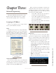
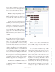
External Sources Page
IP-Intercom sources use an automatic source ad-
vertising scheme so no setup or external software is re-
quired for them.
In most real-word installations, you will want to in-
terface your IP-Intercom system to other non-Livewire
equipment. You can accomplish this easily by using
Axia audio nodes and GPIO nodes and configuring those
External Sources here. These sources might be talkback
from existing analog consoles or interconnections to
wireless intercom systems. External sources could also
be sources that you might occasionally wish to monitor
such as TV audio.
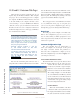
Label
The label may be customized to help you easily iden-
tify these external sources. Keep your label short so it
will fit in the 10-character OLED display.
Livewire Channel
The Livewire Channel is automatically populated
when you select a Source by using the pop-up control
that is located to the right of the Livewire Channel box.
Clicking on this selector button will open a new window
that will list all Livewire sources in your entire network.
Simply select the one that you want to make it available
to your intercom station.
Once a label has been specified and a Livewire chan-
nel selected, clicking Apply will add a new source to
the station.
GPIO Port
This source GPIO Port refers to the port number as
listed on the Livewire GPIO page of the intercom station
configuration. This drop-down control allows you to as-
sociate these channels with AUX GPIO ports 1 through
8. These AUX ports are defined on the Livewire GPIO