
User`s guide
3: Advanced Programming • 20
Version 1.2 July 2010
mode. Of course, since our communication path is full-
duplex, we can Talk and Listen simultaneously so there
is no limitation imposed.
This web page can be used to monitor GPIO activity
in real time so it is extremely useful for troubleshooting
GPIO logic. You must have Java installed before your
web browser can display the GPIO status boxes. They
will illuminate green when active.
GPIO Ports 1 and 2 are special. Port 1 is a hardware
port and can be assigned to any Livewire GPIO function.
It can be used to communicate with other Livewire de-
vices or IP-Intercom virtual ports. Port 2 is a virtual port
used to provide “main” status of the IP-Intercom MAIN
unit itself. The pin assignments are as follows:
1 Listen mode active
2 not used
3 Ring Active (CALLSTACK)
4 Mic Muted
5 not used
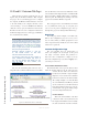
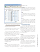
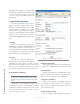
In the example shown in Figure 3-8, we have shown
you a case where we have created a GPIO “snake” be-
tween two GPIO ports. In this case we have used the
loop-back IP address 127.0.0.1 and “connected” the vir-
tual MAIN port with the Hardware Port (the rear panel
15-pin GPIO connector). You can create such a relation-
ship between any Livewire GPIO ports, real or virtual.
In addition to the special functions of ports 1 and 2
we have just discussed, any of the GPIO ports may be
used to map external source logic to a physical port as
we have shown for Port 4.
The parameters for GPIO Configuration follow.
Port #:
Displays the GPIO port number (fixed): 1 through
10. Port 1 is the only physical port. Ports 2 through 10
are virtual ports.
Name:
Provides a box where you can label this port for your
own reference.
Channel:
This is the Livewire channel number associated a
Livewire source that has associated logic (such as a mi-
crophone in an existing Element console) or the GPIO
address and port associated with an external intercom
source. The channel number is entered manually.
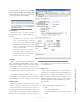
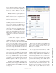
Network and Quality of Service Page
The settings on this tab are advanced settings, and
generally the default settings should be used.
Livewire Clock Master
Livewire’s clocking system is automatic and largely
transparent to end users. By default, the Axia hardware
node with the lowest Ethernet IP address will be the
clock “master”. The system will automatically and trans-
parently switch to a new unit as clock master if needed.
We do however, permit you to force clock mastership
to a particular node or set certain nodes as “preferred”
for clock master while maintaining automatic opera-
tion. For example you may prefer to have nodes that are
on UPS power be preferred clock masters. Note that in
the automatic modes, the clock master is changed only
when the current master becomes unavailable (adding a
new node will not change clock master regardless of the
new node’s setting). The only exception is the 7 (Always
Master) setting.
You have the following choices for this setting:
• 0 (always slave) “STL” – Unit will never be
master and is only used with Ethernet radios.
• 0 (always slave) – This unit will never be used
as clock master.
• 3 (default) – The usual setting.
• 4 (Secondary Master) – Nodes with this setting
will be used as clock masters before those set
to 3.
• 5 (Primary Master) – Nodes set to this setting
will be used as master before those set to 4.
• 7 (Always Master) – This forces a particular
node to be clock master, even if another node
is currently clock master. If this mode becomes
available then the usual prioritization is used.
• 7 (Always Master) “STL Snake” – This forces
a particular device to be clock master. Use only