
User`s guide

3: Advanced Programming • 24
Version 1.2 July 2010
Factory Reset (OLED panels only)
If it is necessary to reset the unit to factory defaults
for any reason, this can be accomplished by powering
up the unit while the rear-panel ID button is depressed.
Once the unit boots up, you will be prompted “Reset in
10 seconds” and if you continue to press the ID switch,
the unit will reset to factory defaults and reboot.
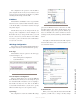
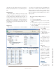
After the reboot, you will then be prompted to enter
the IP address and subnet mask. The first four OLED
displays are used to display the four octets of the IP ad-
dress or subnet mask, depending on which you have cur-
rently selected. Once you have assigned an IP address
and subnet mask, you may connect to the unit with your
web browser and continue with other aspects of the con-
figuration.
Pressing the ID button at any time will bring up the
IP setup screens. Press the Mic or Spkr key below the
fourth display to Save or Cancel your settings.
Display Tests
This section describes tests that may be used to trou-
bleshoot controls, displays and indicators on your inter-
com panels. Press and hold ID button for 10 seconds to
activate the front panel OLED test. Press the ID button
again when you wish to exit test mode.
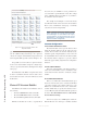
OLED Front Panel Test
• Net, Sync, Livewire, Master LEDS should turn
on and off, one after another and repeat this pat-
tern as long as the test mode is active.
• Press every button on the front panel. A Talk
button press lights up the red LED and turns
on all pixels on the adjacent OLED display. A
Listen button press turns on the adjacent yellow
LED.
• When a numeric keypad key is pressed, that
character is displayed on the auto-answer sec-
tion OLED display.
• The rotary knob values are displayed on the
auto-answer section OLED display as they are
turned. Pressing the knobs lights up the “LINK
ACTIVE” LED. Other buttons of the auto an-
swer section light up the adjacent LED.
• Pressing MUTE SPKR and MUTE MIC, lights
up adjacent LED.
Legendable Buttons Front Panel Test
• The Net, Sync, Livewire, and Master LEDs
should turn on and off one after another and re-
peat this pattern as long as the test mode is active.
• As you press a film cap button on the front panel,
the color of the button will cycle through off,
green, red and yellow with every press.
• The rotary encoder controls the brightness of the
LEDs. As the control is turned, 16 different lev-
els of brightness should be observed.
• Pressing the rotary encoder will toggle the color
of all buttons between green and red.
• Pressing MUTE SPKR and MUTE MIC, lights
up the adjacent LED.
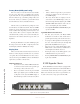
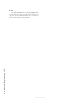
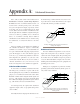
IC.10X Expander Chassis
The IC.20 IP-Intercom station may be equipped with
a 10-channel expander unit known as the IC.10X. This is
a rack-mount chassis with only an AC receptacle, an ID
button and a Livewire jack on the rear panel. There are
no audio connections or logic ports on the IC.10X.
Figure 3-11: IC.10X - Expander Chassis