
User`s guide


3: Advanced Programming • 29
Version 1.2 July 2010
Each virtual GPIO port has a Name box where you
may enter any name to describe the port. It also has a
Channel box where you will enter the IP Address and
port of a GPIO node. For example, you would enter
192.168.0.120/5 in the Channel box if you anted to as-
sociate a Virtual GPIO port with port 5 of a GPIO node
(or Element) with an IP address of 192.168.0.120.
Please refer to Appendix B: Connecting GPIO for
more details and a real world example.
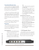
Intercom Livewire Sources
IP-Intercom sources use an automatic source adver-
tising scheme so no setup or external software is required.
You may also wish to interface your IP-Intercom sys-
tem to other non-Livewire equipment. You can accom-
plish this easily by using Axia audio nodes and GPIO
nodes and configuring those sources in this section.
These external sources might be talkback from exist-
ing analog consoles or interconnections to wireless in-
tercom systems. External sources could also be sources
that you might occasionally wish to monitor such as TV
audio.
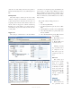
Label
The label may be customized to help you easily iden-
tify these external sources. Keep your label short so it
will fit in the 10-character OLED display.
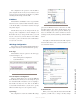
Livewire Channel
The Livewire Channel is automatically populated
when you select a Source by using the pop-up control
that is located to the right of the Livewire Channel box.
Clicking on this selector button will open a new window
that will list all Livewire sources in your entire network.
Simply select the one that you want to make it available
to your intercom station.
Once a label has been specified and a Livewire chan-
nel selected, clicking Apply will add a new source to
the station.
GPIO Port
This source GPIO Port refers to the port number as
listed on the GPIO Configuration area of the intercom
station configuration. This drop-down control allows
you to associate these channels with AUX GPIO ports 1
through 8. These AUX ports are defined on the Livewire
GPIO configuration page that was discussed above.
Talk and Listen pins are selected by the associated
drop-down selector. Pins 1 through 5 are available.
Each external source GPIO port is assigned separate
Talk and Listen pins that will allow you to interface these
sources to the real world. Since each port has five pins,
you can double-up two sources on a single GPIO port (2
talk pins and 2 listen pins.
Talk Pin
A contact closure to this pin will replicate pressing
the front panel Talk key associated with this source.
Listen Pin
A contact closure to this pin will replicate pressing
the front panel Listen key associated with this source.
It is very important to understand the logic of Talk
and Listen as they apply to local and remote users. A
local Element user will press Talk when he wants to
talk. A remote user will place the Element’s IP-Intercom
channel into Talk mode when he wants to Listen to the
Element operator. This seems a bit strange but it is the
same way a conversation takes place. At any given point
in time, one user is talking while the other is listening.
When the Element channel is in Talk mode, the Ele-
ment’s Operator is talking and the remote user is listen-
ing to him. The same logic follows through to the Listen
function. When the CR Operator must Listen when the
remote user Talks - so in order for this exchange to take
place, the Element’s IP-Intercom station must be in Lis-
ten mode. Of course, since our communication path is
full-duplex, we can Talk and Listen simultaneously so
there is no limitation imposed.
NEW
Additional Livewire sources can be added to the list
of external sources by entering the relevant information
in this row and then clicking the Apply button.