
User`s guide
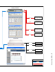


Connecting GPIO • 33
Version 1.2 July 2010
Appendix B: Connecting GPIO
This Appendix will give you some basic informa-
tion on GPIO (General Purpose Input Output) ports.
Please refer to the manuals supplied with your Element
or GPIO node for more details on integration with other
non-intercom GPIO.
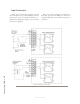
GPIO Port Definitions
Axia GPIO devices utilize DB-15 connectors on
their back panels. Each connector (also known as a
GPIO port) can be associated with the logic functions
of a device in your studio. Each GPIO port and provides
five opto-isolated inputs and five opto-isolated outputs
per device for machine control, lamp drives and remote
channel controls. GPIO ports can also be monitored and
controlled by our PathfinderPC software.
GPIO ports are programmed to support several dif-
ferent types of devices. How does a GPIO port “know”
which type of device is assigned to it?
When you construct a console Source Profile for a
telephone hybrid, for example, you defined the source
type. This is important, because when that source is
assigned to a console fader, Element console uses this
Source Profile definition to tell the GPIO Node what sort
of command to send to the attached device. IP-Intercom
stations are also a special type of source that have pre-
defined GPIO properties.
If Element “sees” in the Source Profile that the as-
signed device is a microphone, it tells the GPIO Node
to send logic for On, Off, Remote Mute and Remote
Talk commands on the appropriate pins as defined for
a microphone source. If it “sees” a line input, it tells the
GPIO Node to send Start, Stop and Reset commands,
plus closures for Ready lights, etc.
Axia GPIO ports can deliver unique command sets
for the following types of devices:
1. Microphone (Operator, Guest, Producer, Talent
or External)
2. Line Input
3. Codec
4. Telephone Hybrid
5. Computer Playback Device
6. Control Room Monitor
7. Studio Monitor
8. Profanity Delay Device
9. Recording Device
10. Accessory Button Panel Device
11. IP-Intercom Station
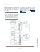
The pin definitions for the IP-Intercom hardware
port are provided below.
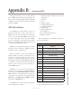
IP-Intercom GPIO Connector Pinouts
Pin Function:
1 Listen Active Lamp
2
3 Ring Lamp
4 Mic Mute Lamp
5 Line Active Lamp
6
7
8
9
10
11
12 Mute Preview/Speaker Command
13
14
15
The functions of the pins vary a bit for different de-
vice types. This automatically customizes the port to the